Mains filtering: a great idea which falls flat in practice
On another page we said "mains power filters are infra dig., by the all-powerful Law of Inconvenience which holds sway over the Flat Earth. For good reason, too - they all make a mess of the music."An extraordinary claim, so we'll qualify it some more: having tried many variations on mains filtering and 'treatment' - for hifi they suck.
Take a look at the typical equipment filter, pictured left. Mains Input is on the left, Mains output to supported equipment on the right. First there's a large value Cx capacitor, usually in the range 0.047 - 0.1uF, occasionally up to 1uF depending on application. Not shown, but a wise precaution, is a high-value resistor in parallel with the Cx cap, c.100-250Kohms, to ensure the cap is discharged when the equipment is unplugged to prevent a shock off the plug pins. Then comes the 'current compensated' inductor. As you can see the two windings are opposite hands, so in normal use the magnetic fields cancel and the choke has a very low net inductance. If the incoming noise is common-mode w.r.t earth, the noise current flows through both halves in the same direction, the inductance presented is high so resisting the noise current. In high-current variants, and at least one well-known for-audio filter design due to Jon Risch, the common-mode choke is replaced by two separate inductors, to deal with differential mode noise. The inductance is followed by the Cy caps. - usually in the range 1nF to 4.7nF, which are to deal with self-generated noise. Note that there is a cap between Neutral and Earth even though these two are physically-tied together elsewhere in the mains wiring system. It is necessary because real-world wiring inductances present considerable impedance to high frequency noise currents.
So far, so good: nasty yobbo electrons in on the left, with neatly groomed and scrubbed electrons marching orderly out of the right hand side - or so some hifi 'accessory' sales-pitches would have you believe! Well it just ain't so; unfortunately the insertion of such a filter seems to squash dynamics and the natural, rhythmic expression of music; this applies to ferrites on cables too. Quite why, I'm not sure - which is where I break off into speculation: I think it has to do with the effected and reflected impedances after the filter 'seen' by the equipment.
Before anyone says 'it's only 50Hz, so impedance doesn't matter' take a look at what is really demanded by (and reflected from) a linear PSU under heavy load. For amplifiers, which draw large charging peaks (implying high-frequency, high current content) under load, there is a fairly obvious mechanism: the drawing of high current pulses is effectively resisted by the inductor, which effectively raises the whole PSU impedance - squashing dynamics. One answer may be to use a filter whichis grossly oversized for the application (10 or 15A+ rating) but there's a second mechanism at work which I suggest affects all attached audio equipment.
Noise currents extend right through the audio band, due to rectifiers and the high dI/dT (rate of change of current at the charging peaks). Current flowing through an impedance creates a voltage, so to prevent these noise currents interfering the raw supply needslow impedance. The Cx and Cy caps in our filter attempt to do this by presenting an effective short circuit at high frequencies. Yet a quick bit of modelling of the mains-supply based some real-world impedances will show that if you add, say, 1 or 2uF cap across the mains what you end up with at that point is actually an impedance peak in the supply, smack in the audio midrange or just above in the 'brightness' range(4-10Khz); go figure. Note that Cx caps in other equipment plugged-in close to the audio equipment will present this effective peaking mechanism - an explanation for the observed slight negative effects of the Linn Lingo on Naim systems, perhaps? In my experience it appears audio equipment responds better to the smoothly-rising impedance of the unfiltered mains despite the potential for influence by incoming and self-generated noise.
Don't try this at home
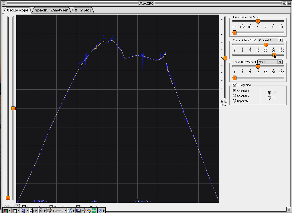
June 06 update: while taking the measurements shown on the mains-borne noise page I did a quick-and-dirty test for general edfication and to back up the statements above.
Out on the WibblyWobblyWebnet in other sites are suggestions of DIY fiters based around adding gobs of capacitance across the line in an effort to filter out this noise and even more dubiously, provide a ' flywheel effect' *. One such 'megamanger' of an idea uses an 8uF cap; there are also commericial devices sold which comprise 1uF caps in plugtop boxes with the intent of you adding several distributed around the house, to basically the same end result. Which is this:
Raw mains feed is the fawn colour, and the blue is the result of solely adding a 10uF/440VAC capacitor to the adjacent wall socket. Now, what were we saying about additional noise created in the supply due to unwanted interactions...?
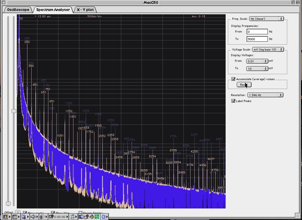
The 'filter/flywheel' cap clearly interacts badly with the supply and other loads in the house, leading to far more noise with than without! And look, the noise increase starts at 250Hz (5th harmonic) and extends right through the midrange. Is this why the sonic effect can be so unflattering when used on hifi ? For what it's worth this test was on a double socket on the end of a radial off the consumer unit, not shared with other equipment. The traces were averaged over a minute in each case, hence the extensive 'skirting' on the unwindowed spectral plot above (which I picked at random from the ten or so runs repeated over a few days - and which all turned-in the same result...)
For the terminally curious, increasing the capacitance to 20uF certainly didn't improve matters...
(* As for that whole flywheel idea - it's bunk. AC current in a capacitor leads the applied voltage by 90degrees, which means current available is at a maximium when the AC is at the zero-V 'crossing'. Unfortunately, electrical equipment like amplifiers draws current only in 3-5 milliseconds bursts at the mains voltage peaks, when the internal PSU diodes conduct. So charge stored in the cap is never available to help out the PSU drawdown...)
A slightly different approach
I've built and tried zobel-like networks too, series RC networks to try to negate this peaking by smoothly rising to a resistive limit. I could not hear the usual degradation from mains filtering, halellujah (and I did try). On the other hand there were no readily- discernable benefits either! I discarded the approach on the K.I.S.S principle. I'll post the spreadsheet for this whole idea to the acoustica site if anyone is interested. For those interested, try 1uF in series with a 47-50ohm, 3W resistor across L and N. Use only suitable mains-rated parts in a double-insulated enclosure. You can't listen to music when charred and crispy, and neither can your loved ones; if you can't tell what is suitable please ignore this whole suggestion.
A quick word on isolation transformers
The best results I've had after six months of messing-about, is using a big, high quality transformer set up to provide 'balanced power' i.e the equipment earth is the transformer centretap, no direct connection to mains earth. That one with the whole system powered off it actually preserved most of the music, but altered the sound unacceptably; it all went very 'dark' - a subjective lack of energy in the mid/high frequencies. Normal (and quite flash!) isolation transformers affect things as well - having heard the difference these make in a few systems now, I really couldn't recommend them, and this does NOT just apply to Naim gear. When I've heard immediately apparent 'improvements' from the use of isolation transformers I would lay good money it's actually down to the rise in effective supply voltage to the powered equipment. Transformers have worse regulation (higher impedance) than the AC mains by at least an order of magnitude. The output voltage is specified under full rated load, and it tends to rise somewhat when only powering a light load such as an audio system. Bigger transformers have lower impedance, essential for best results with audio, but tending to more spectacular voltage rises (despite generally tighter regulation than smaller transformers) because they are effectively unloaded. If your system sits at the end of the foodchain mains-wise, the apparent difference between mains at 225v and 250v is not subtle. Then, seduced, you wind the wick up, and the heavy transient currents - necessary to charging linear PSU caps in the amplifier - effectively modulates mains voltage to all the supplied boxes due to that high impedance. As a result the sound hardens up, and it all goes to pieces. That positive-ish result only came from using a very small power amp with a very big transformer ...
© the twisted pair 2004