Inveterate meddling #377: Quick notes on using 3-Pin Voltage regulators
or at least - some things the application notes don't make obvious
Many of the tweaks and mods on this site and elsewhere are based around providing 'cleaner' power supplies to the many separate elements which comprise audio systems. In essence, this works because a 'clean' supply is one which i) contributes as little excess noise as possible and ii) has a very low output impedance, so that it interacts with the powered circuit as little as possible by forming a 'perfect' source and sink for all currents. The backbone of clean supplies is voltage regulation, and the workhorse of cheap and easy regulation is the humble three-pin regulator...

|
Consider the LM317T: used everywhere, cheap, effective and preferable to the fixed-output, 78xx type because it offers superior ripple rejection and output current at little premium. But how can we squeeze the best performance out of it? To begin with, a couple of links:
LM317 datasheet
Using the LM317, an excellent overview by Werner Ogiers, with many details and measurments - and some alternative regulators investigated. You must Read This First!
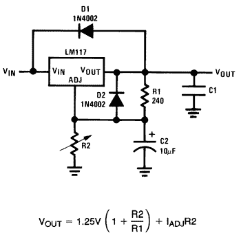
Shown left is the typical application-note schematic for implementing an LM317. Higher-current versions (e.g. the LM338) and even other adjustable types such as the LT1086 are fundamentally identical in function - so you can read these pages as applicable to all of them. and to the complementary LM337 also (pin-out changes being observed!) For any of these regulators, a brief recap:
Vout is set using the ratio of R1 and R2
C1 is recommended to deal with load transients, as is a small (0.1 - 10uF) cap to ground at Vin if the reg is more than 150mm from the raw supply reservoir capacitor.
Better ripple rejection is secured by adding the capacitor C2 across R2.
D1 and D2 are recommended to protect the regulator from the effects of stored charge in C1 and C2 at switch-off, or if the raw supply fails.
The datasheet doesn't explain why adding C2 improves performance...
|
In a nutshell, the output voltage adjustment works like this: the 317 actually only regulates the 1.250v across any resistor placed between VOUT and VADJpins (R1). By Ohm's Law this sets a constant current through R1, which multiplied by R2, fixes the voltage appearing across R2. So the regulator's output voltage is the voltage across R2 plus 1.25v. (Note there is also a small, constant, current used by the 317's internal voltage reference - typically 100microamps - which flows out of the ADJ pin to ground, and the formula above also includes for this. Effectively it is an error term, and so has little bearing on this discussion.)
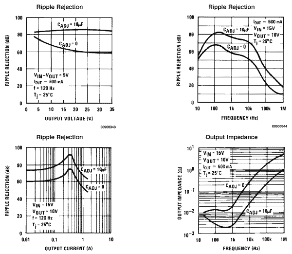
So, by inspection, we can see that C2 bypasses R2, and this stabilises the voltage 'below' the adjust pin which the 317 'sees' or stands upon if you like. For the sake of 1 additional, cheap part we get significant improvements in performance, about 20dB or 100x drop in ripple breakthrough and output impedance:

Actually, it's a bit more interesting than that. To be pernickety, C2 doesn't just stabilise the voltage appearing across R2, or decouple noise out of the 317 somehow, but rather it plays with impedance in a way that helps performance.
Look at it this way: the 317's reference voltage is based on holding an accurate 1.25v across R1. This is multiplied by (R2/R1) to get an output voltage of 1.25*(1+(R2/R1)). In effect, R2 adds positive feedback from the sum of R1 current and the internal voltage reference current! What C2 does is bypass (reduce) this positive feedback: effectively it reduces 'noise gain' to the internal amplifier. At DC, the voltage gain remains R2/R1, but to AC signals the voltage gain tends towards (1+ 0/R1) = 1 because C2 'looks like' a very small impedance at high frequencies. This lowered noise gain is where the much better ripple rejection shown in the LM317 (and similar parts) datasheet comes from. So, a big hint: make Z (the impedance) of C2 much smaller than R2 at twice your AC Mains frequency to suppress ripple better; 10uF will be more effective than 1uF for example, and 100uF may be better still.
Knowing this we can obtain even better performance out of the humble LM317 and the like, and here's where we go off the beaten track: The trick is to retain C2 but replace R2 with something like a zener diode. This brings lower noise all the way down to DC - because the dynamic impedance of the zener will much lower than the required value of R2 to achieve an equivalent output voltage. Effectively this stops the pairs of curves on the ripple rejection and output impedance graphs above converging again at low frequencies; you can picture this as mimicking the action of a truly enormous 'perfect' cap at C4 without the cost. Using a zener diode of voltage Vz then the final output voltage will of course be (Vz+1.25)volts.
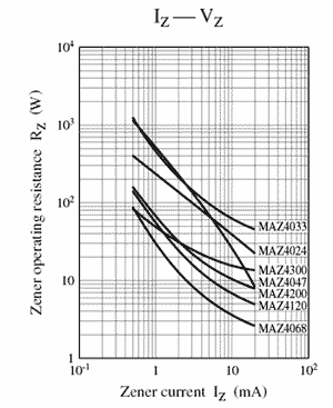
Now look at this graph:

This is for Panasonic MAZ series zener diodes, but the numbers are very similar for comparable parts up to 1watt e.g 1N9xx series parts. As can be seen, impedance drops slightly when pouring more current through the diode in reverse. Typically, Iz, the rated dynamic impedance, is about 30ohms for a 3.9v zener at 20mA; a 15v part would have a dynamic impedance c20ohms, just 1/50th that required using a conventional R2 resistor. If you like, try increasing the current through this zener - reduce R1 to say 68ohms. The dynamic impedance of teh zener is reduced and then the ADJ pin 'sees' a maximum of c.10ohms effective impedance to ground. Better and better, but wtahc for powwer disspation in the zener at higher voltages ( P=I x V). For example: R1 = 68R at 24v is 20ma, or 500mW dissptaed in the zener - so use 1.3W zeners.
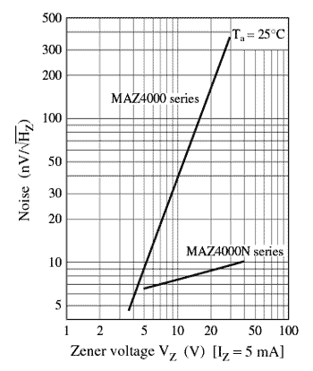
Also worth considering is the zener noise density graph:

Whilst 'everybody knows zeners are noisy' - even without C2 the noise density is actually rather lower than the conventional LM317 offers (typ. 330nV/sqrt(Hz)) - and it drops with increased current through the zener. At the 12mA reference curent usual with an LM317 (i.e R1=100ohms), the 317+zener combination typically produces just 1/5 - 1/8th the output noises of using R1/R2 as given in the datasheet! Keeping C2 benefits here because it will reduce (decouple) excess noise contributed by the zener.
One tip - using a zener in series with a normal diode (cathode to 0v), and you get nearly-perfect temperature compensation for free, too, because the zener avalanche voltage has a positive temperature coefficient, whilst the junction diode has a negative temp coefficient that nearly equates. The extra diode adds 0.6v to the output voltage of course.
For 5V output, a useful substitution is to use two green LEDs in series. These will drop about 1.94v each, or 3.9v across the two, with lower impedance than a 3.9v zener - which makes the output voltage setting more accurate, and with lower noise since the leds are forward-biased PN junctions. You also get bright green light to let you know the reg is working...
Best of all is to use a dedicated fixed reference, such as the LM329, to set the LM317 output voltage - if the resulting voltage suits your purposes. An LM329 can have a dynamic impedance c.1ohm. But at this point, we've spent more on supporting parts than the basic regulator cost... and for only a little more we could investigate altogether better solutions...
Finally (on this page, anyway), how about using two regulators in series? More betterer, right? Well not quite. You have to provide another 3 or 4v headroom, for a start, and while the ripple rejection is (in theory) doubled, there doesn't seem to be a commensurate audible benefit.
So the tip is - if you are looking to try two regs in series, try a 'tracking preregulator'. This way the first reg after the raw PSU is not set up to maintain a regulated supply which the second reg is fed from, but rather, set-up to maintain a constant voltage drop across the second reg. There's a diagram in the National LM117 datasheet linked above, and we'll discuss it in detail in Part 4 of this series
It's easier to rig up a LM317 this way if it is physically close to the second reg, but you can do it simply by lifting the 0v end of the (first reg's) lower voltage set resistor and returning it to the output of the second reg. Replacing both the pre-regs voltage set resistors with 1k items will set the voltage across the second reg at 2.5v, quite enough for most purposes. Add the Cadj cap across the lower voltage-set resistor - it still makes an audible difference (i.e this cap is connected between the 1st regs ADJ pin and the OUTPUT of the second reg.)
This gives a quite noticeable (ie audible) improvement over two regs in series. Effectively it relieves the second reg of all line regulation duties - and the second reg benefits from its own (low) output impedance. It's a trick used to great effect in Andy Weekes' super-regulators; just try it...
On to Part Two...
© 2006 the twisted pair
28.12.11 Minor text tweaks for clarity.
28.08.11 zener paragraph updated
2.01.07 Tracking pre-reg tip added.
15.10.06 Typos fixed, LED tip added
6.10.06 Page added


