Misc. reference information:
Inveterate meddling #106: more fun with the Naim CD3.5
So, what else can be done to one of these poor, unsuspecting machines? Quite a lot actually....
|
|
Misc. reference information:
|
1: Replace the opamps in the anti-alias filter and output stages. These stages are built around 3 Burr Brown OPA604 opamps per channel in series, comprising two 3rd-order Bessel low pass filters, and a single low-pass / buffer between. You can replace these opamps with anything better, but Analogue Devices AD8610 are very very good, and BurrBrown OPA627 are simply outstanding here. The OPA 627 is a simple drop-in replacement if used in 8-pin DIL package. The AD8610 is avalable only in a surface-mount package, necessitating the use of adaptors (such as the 'Brown Dog' parts) unless you are very steady handed and able to do the adaptation / pin extension freehand. Few are!
Begin by replacing the two opamps at the output, which work the hardest - these are both 2-pole active lowpass filters and also driving the output load. Dropping- in two OPA627s here is a really nice improvement, cleaning things up nicely. If you like what you hear, replace the remaining four opamps, but the law of diminishing returns kicks-in fast.
One more thing. Fast opamps do NOT like loading with capacitance, which means the interconnect needs to be considered carefully. Naim's own Snaic is rather low capacitance cable, but we can ensure the potential for problems with other cables will go away by adding some 'buildout resistors' in line between the last opamp and the rear panel socket. On the underside of the motherboard, find the traces linking the output cap with the opamp. Cut the track, and bridge the cut with a small value resistor (in the range 22 - 47 ohms). That's all! The resistor decouples the opamp output from any cable capacitance to ground and so reduces dramatically the chance of oscillation due to excess HF phase shift.
2: Upgrade the clock There are any number of aftermarket clocks available, from Trichord, Tent Labs, LC Audio,Audiocom etc. or the DIY design by Elso Kwak. I've had very good results with Kwak clocks here and elsewhere, but better yet is the Tent labs XO module. This device is specified for vanishingly-low jitter, providing you take care with providing a suitable low-noise power supply for it. Once you've sorted out the details, here's where you connect the clock of your choice:
(View from above; components mounted on underside of PCB shown dashed)
The clock is a very neat implementation of a standard Pierce oscillator built around an unbuffered inverter on it's own isolated area of the ground plane. To feed-in a new clock signal remove the existing 16.9344Mhz crystal and two tiny tank caps (10pF ceramic). Remove the small 10Kohm drive resistor. Leave the 220Kohm feedback resistor. Scrape an area of mask off the clock groundplane area - or use one of the topside pads vacated by the little caps -and connect your new signal lead in between the ground plane and the end of the feedback resistor. This provides your new clock signal to the inverter which buffers the clock signal and distributes it to the decoder and DAC on the underside of the board. ( Read item 3 below first though!)
Detail of course is everything. Your clock signal lead should be driven via a 47-75 ohm resistor placed immediately on the output of your new clock (if such a output R is not provided with your new clock source). The clock will require a low-noise supply to get the most benefit - noise on the supply tends to feed right through into the oscillator's phase noise perfomance. Avoid returning PSU current through impedances common with the clock signal. A small separate transformer just to power the clock is recommended since this guarantees galvanic isolation. Note the clock and its supply needs to start quickly so the clock signal is provided fairly early after the machine is turned on (within 1-2secs max.) otherwise the decoder loses control of the servos (typical symptom is the cd motor running up to turbine speed). With a slow run-up due to heavy supply filtering this can be a problem. A simple solution is to tap into the mains feed before the switch in the 3.5 (use an additional 500mA inline fuse!), so that the clock PSU is always live when the thing is plugged-in to the wall. Then, when you flick the unit on at the backpanel, the clock is already running...
Incidentally the rule of thumb for jitter contribution by logic gates is 1nS / volt, that is, 1volt of noise on the supply adds 1nS of correlated jitter. Since we desire 0 jitter, the supply noise performance has to be correspondingly good... this leads to tweak 3:
3: Lose the Inverter This is the obvious postscript to step 2. Using an aftermarket (or DIY) clock you can avoid using the 74HC04 clock buffer altogether. This if done right, is a very good thing.
The inverter in the 3.5 both generates the clock and distributes it to the SAA7376 decoder and TDA1305 dac. Trace the connection between the inverter and the two other chips and you'll find a 50ohm resistor linking the inverter to the DAC, and a 330ohm resistor linking the inverter to the decoder. You can remove these and feed you new clock signal in directly to both these chips like this:
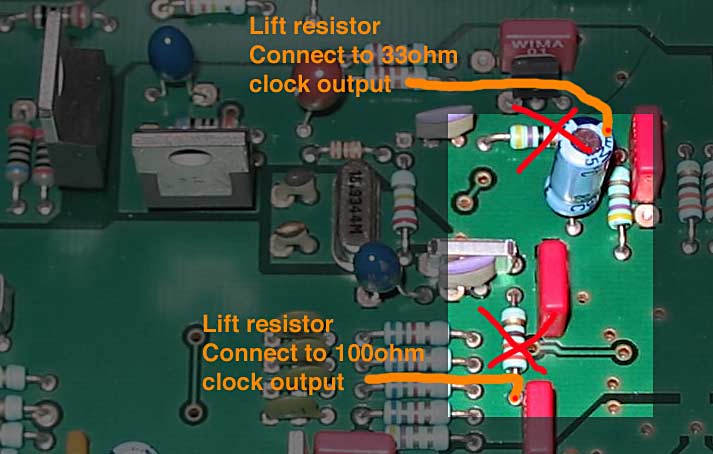
This removes the inverter and its PSU from the jitter morass, but be careful to avoid common impedances and do the new connections right. Locate the via which forms the DAC's connection to the ground plane. Scrape an area clean close to this, and connect your main clock signal into the dac with miniature coax cable which connects the shield (clock 0v return) to the area scraped bare. Take a second min. coax from your clock output to the decoder clock input, but leave the coax shield floating at the mother board end - you only want one connection between the clock's groundplane and the 3.5's digital ground. Remember both clock coaxes should be fed via separate resistors for the clock output (R value to match the coax characteristic impedance, typically 50 or 75ohm).
In fact the optimum series resistor rather depends on the impedance of the connection, the load (capacitance) that the receiving end presents, and the output impedance of the driving end. Using a fast oscilloscope I found that (for my implementation using a Tent labs clock) the best waveform was preserved using a 33ohm resistor at the clock end for the clock signal to the DAC. I also needed a different value for the decoder input - I settled on 100ohms, but up to 330ohms (as used by Naim between the inverter and the decoder) is good (these are the values referred to on the picture above) Now you see why the Naim picked their values... it seems the decoder gate has quite a large input capacitance. This means it will draw quite a high peak current when the signal changes state - and sudden changes in current mean stray voltages appear across even short lengths of wire due to inductance.
Example: 10pF input capacitance, fast signal rise time of 2nS to 5v. CV=IT, so current peak is (10pf*5v)/2nS, or 25mA. Induced voltage is L*dI/dt; that works out at about 0.7v across just a piece of wire 75mm long... that's a lot of overshoot on the signal, added by just a shortish connection. Adding a series resistor cuts the current right down, slows the rate of rise and thereby controls the overshoot - it cleans up the signal.
So while it might be a hassle, it's worth it - getting rid of the inverter is a great improvement! If you install a new clock and bypass the inverter all in one go, all you need to do to isolate the existing clock is lift only the two resistors identified above leaving the crystal, 10pF caps etc in place. Then if it doesn't work you can always reinstate the entire original clcok setup easily, by refitting tthe 50 and 330ohm resistors.
4: Upgrade or augment the PSU supply decoupling to the TDA1305 DAC. Unlike the CD63 described elsewhere on this site, Naim really did their homework on the layout and parts spec. On the DAC, Pin1 is the analogue supply, Pin 10 the digital supply and pin 28 the internal opamp supply. All these are supplied from three separate LM317 regulators giving 5.0v via series resistors (2.2 - 3.3ohms, depending on location), with local decoupling local at the DAC pins.
There are still some gains to be had here. It seems pin 28 benefits most from a better supply; pin 10 makes no tangible difference (if it did something would be seriously wrong!) and pin 1 supplies the internal current-source gubbins, which is subsequently steered by an internal voltage reference. You can trace and locate the 10uF tantalum cap supplying pins 1 and 10 and replace with Sanyo OsCons; leave the Wima 0.1uF film caps in parallel. Now locate the caps on pin28 (the internal analogue output stage). Remove the 10uF tant and the 0.1uF Wima film cap, and replace with a 100-220uF Oscon in the location formerly occupied by the red wima cap close to the chip. Follow the supply trace back toward the LM317 which supplies pin28 You'll find a 3.3ohm resistor in series. Reduce this to 0.5ohm (two 1ohm R in parallel), but not less or the oscon will lead to noise peaking with the effective output inductance of the LM317, which varies with current drawn...
This little lot together reallybrings up resolution and musical 'bounce'.
5: Decouple Vref
The Dac is a Philips TDA1305, which has its own internal current sources continuously calibrated. Now then - the really nice thing about the TDA1305 is that the internal voltage reference ( nominally at 0.5 x Vdd - in other words, 2.5V) is brought out to an external pin for additional decoupling on pin26. Philips recommend a 1uF cap here - the reference draws tiny currents, but switching is at 96Fs (= 2.1Mhz), so the noise is wideband.
The datasheet says:
Internal reference circuitry ensures that the output voltage
signal is proportional to the supply voltage, thereby
maintaining maximum dynamic range for supply voltages
from 3.4 to 5.5 V and making the circuit also suitable for
battery-powered applications.
...
Vripple = 1% of supply voltage; fripple = 100 Hz. Ripple rejection RR to VDDA
is dependent on the value of the external capacitor (CEXT3 in Fig.1) connected to Vref.
The value here assumes that CEXT3 = 1 uF.
I did try building an external buffer to keep impedance low here - basically, an active reference follower based around an OP27 to brute-force pin26. It's something that DPA did in their dacs - it seems that keeping any LF modulation off the voltage reference really helps in bass quality and extension. However this method does hold out the potential to kill the DAC if anything goes wrong, so I can't recommend it when a big Oscon is more reliable, simpler, and appear to work at least as well.
6: Coupling caps There are two pairs of coupling caps, all the little blue 10uF tantalums caps. These are located linking the DAC outputs (pins 22 & 25) the ouput stage, and connecting the outputs stage to the rest of the word near the output relay. If you have a favourite coupling cap, it could be worth trying in these locations. 10uF PPS types are stupendous, if you can find them and make them fit. Be aware if trying electrolytic types (Silmics), the stage design is single-rail, so all these caps are polarised.
Note there are two more 10uf tantalums, located halfway betwen the pairs mentioned above. These only decople an intermediate bias stage and are not critical to sound quality.
7: Analogue stage bias One more thing while we're discussing decoupling: at the input to the analogue stage after the coupling cap is a pair of resistors in series (160K each) that restore the DC level to half the rail voltage before the first opamp. Just as in the Naim line stages, these are connected directly to the gain stage (opamp) supply rail when it should not be unfiltered, so here's how to cut the noise injection by more than the standard -6dB(!!)
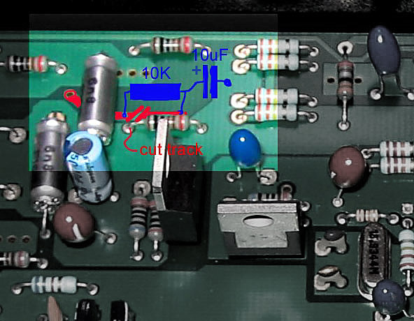
Cut the track coloured red, bridge the cut with a 10K resistor, and tie the 'bias' end to ground via a 10uF -100uF capacitor (type and value not critical). There, that's it - rail noise is now removed from the analogue signal in both channels. Incidentally, I'm thinking this is one reason why the 3.5 gains so much from better regs internally - lower rail noise means less rubbish mixed directly into the wanted signal here.This is a must-do mod.
Incidentally there is a second bias network before the middle pair of opamps, but these already have a 10uF tantalum cap decoupling for each channel...
8: Don't bother with improving regulation for the purely-digital 'front end' - the microprocessor and other purely -digital devices. These already have independant supplies (built into the player) from the output stage - you are using an off-board supply already, aren't you?. Digital control signals have no bearing on the quality of sound that results. Substantial changes, including superregulation here have already been tried by others (hi Ced!), who report no benefit.
So, there you go: how to turn a very good player into a truly great one ;)
Have fun!
© the twisted pair 2003-6