biased!
Spurred-on by this Pink Fish Media thread, here's a quick investigation of the link between the quiescent bias-current setting and linearity, for the Naim quasi-complementary Class-B power amp design.
As I posted in that thread, 'measuring the total current draw of an amp is actually a pretty imprecise way of setting bias - for which the only thing matters is the current at the output transistor and specifically the voltage across the emitter resistors - Doug Self has published some pretty exhaustive analysis of this for many different output configurations. If you change the operating voltages, the PSU 'stiffness', regulation of the front end or better definition of its operating current, the temperature at which all the BJTs operate... you change the balance of the total amp current draw to the output stage in dynamic and untested ways, probably quite radically. Naim amps don't have thermal compensation for the bias setting, due to the quasi-complementary output stage, which is why it's critical to 1) set them warm and 2) not to run too high a bias - potentially they can run away thermally. So it's entirely possible that with a heavily modified amplifier, a different bias (from the usual advice of 36-38mA total on the positive rail) set by total current draw is correct - because that's what it will take to get the particular output stage into its sweet spot.'
A test case
So - the right place to measure, and therefore set bias, is by monitoring the voltage appearing across the 0R22 emitter resistors. So we're going to measure the effect this setting has on distortion.
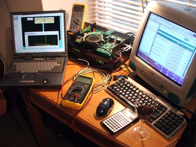
The Nait 2 uses the same basic architecture as all Naim power amps up to the 250.2, and it's got a handy level control bolted on the front, and it' s the only Naim amp I have to hand, so here goes... I wrote a 1hr track of 1Khz, 0dBfs sinewave to CD using a utility on the ancient iMac. So, we have a source potentially capable of less than -93dB THD (0.0022%). This was read by my long-suffering CD2, and the signal fed to the Nait2. Here's a picture of the setup; note the glass of cheeky young Rioja:
At the Nait's output, a dummy load was plugged-in, comprising 2 x 10W, 12ohm metal film resistors in parallel for a 6ohm, 20W dummy load:
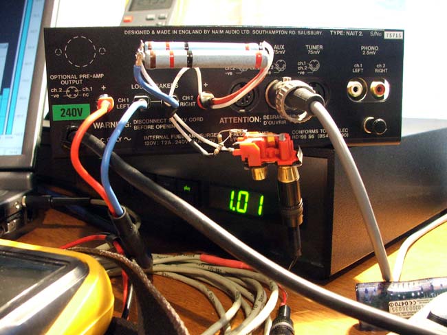
Attached to this load is a resistive 100:1 attenuator (in the white wires) which in turn feeds the input of the craptop's soundcard. This input is analysed using SpectraRTA for real-time %THD analysis (and a few other things I'll write about some day). The large DVM is temporarily soldered to the Nait to set/monitor DC mV across an emitter resistor. So - full-scale signal into the Nait, volume control used to set power output, and the Nait's balance control was used to null-out channel differences to within 5mV so that the second DVM plugged into the other channel monitored Vrms across the load. This was arbitrarily set to 1W into 6ohms (2.450VAC rms) at 1Khz during testing. Room temp was within 0.5deg C all evening, and the transformer-powered halogen and CRT iMac turned off during testing to avoid stray fields as far as possible.
Method: with the amp warmed for 2hours (pink noise at 5W/10mins, followed by 1W continuous) I took an initial distortion reading as-was to sget a baseline: 6.9mV of bias; 00171%THD, at 1 watt into 6ohms. After this, the test regime was simple if tedious: adjust Iq by measuring mV across an emitter resistor; allow to stabilise 1min, readjust if required, then run CD input taking the THD% figure after 30secs (slowest averaging used in software, last significant figure discarded). Pause track, Iq re-checked, then reset for next test (pot swung back to centre of test value) The bias figure was also checked 5-10secs after the test track was stopped to ensure nothing too radical had gone wrong. It was quite noticeable that %THD drifted after10secs or so under load, indicating bias drift as the amplifier's temperature changed - though it could not be sensed on the heatsink - and thi swas reflected in inflated mV readings that drifted down a few tenths after stopping the test input. Also note that shifts of 0.2mV could be easily and immediately arranged by blowing gently on the circuit! After pausing the test track it would take 10-30secs for the bias to settle again, however 3mins were allowed between iterations to ensure DC values. Waiting for these 'thermal tails' was the most boring bit of the testing.
This is where the Rioja came in.
Total distortion levels averaged around -76 to -80dB at 1 watt, pretty respectable overall given it's the sum total of 1) my home-bodged CD2, 2) the Nait and 3) A-D conversion on a crap laptop 4) manky bits of wire and the hasty lash-up bolting these bits of kit together. In any case the numbers should be viewed as relative NOT absolute. At the end of the session - and 3hrs after I started - with the bias reset where it was to begin with, the amp measured the same as when I started, so my errors appear to be monotonic at least...
To cut to the chase:
Here's what happens when you test %THD against the quiescent bias setting measured in mV across one 0R22 emittor resistor. The curve stops at 8.5ma becaue experimentation significantly beyond here brought no substantive change (except that I had to open another bottle). So why should we care? Well apart from anything else the curve shows:
So - based on a sample of one(!) - the recommendation is simple: make sure your Naim's output stage displays at least 4.5mV across a 0R22 emitter resistor that is, Iq around/up to 20mA here; more accurately - aim for 8.0 to 8.9mV across BOTH emitter resistors. Provisos are 1) just don't worry if it's within the 4-6mV range and 2) don't waste a lot more bias current in the hope of lower distortion, it only risks thermal runaway and does not improve matters. That's all!
One last thing: certainly don't turn the wick right up in the hope of 'Class A' operation. No, really, don't do it.
Well, since you asked...in the interest of research... and with a little adjustment (ahem) this Nait was temporarily fudged to just squeeze the necessary 90mV of standing bias to run the test entirely in Class A. Result: 0.0135% THD, when just 7.0mV of bias resulted in 0.0165% THD! Note though, that the bias was galloping away while I watched. The 90mV bias setting represents nearly 400mA of standing current, and the meter drifted well past the 500mA mark in under 15secs of the very abbreviated test run. Left unchecked the amp would have blown in short order. Now look at the 'benefit': a difference less than 0.003% (< -90dB difference) but with the certainty of killing the amp. So don't believe anyone that says adding more bias is better.... without checking all the possible consequences in detail.
© the twisted pair 2007; contact us