
Tools & Materials
Misc. reference information:
hack the Planet!
Rega's iconic first CD player was (and in mark2 form remains) the mid-price player to beat. When compared with the very best it's a little flat dynamically, slightly restricted in bandwidth and not the last word in resolution. But this is a typically Rega product- it just turns out music and engages the heart rather than the critical faculties. And all at a price that makes many an alternative look silly.
The Planet is built around four simple building blocks; a regulated PSU; a Sony CD mech and decoder board, rigidly mounted to the top half of the die-cast case; a BurrBrown PCM1710 DAC; and a Sanyo LA9216 single-chip stereo CD output amplifier stage (the datasheet is not available form Sanyo, but the related LA9215 datasheet is - see below). That's all. Like the Nait2, the Planet a giant killer in the sense of showing most emperors to be naked. Also like the Nait, the Planet is possibly greater than the sum of its parts, so don't go expecting miracles from a few DIY mods...the results may still surprise though! The menu below ranges from the very modest through to a full reclocking. However if you simply want a little more of what the Planet already does then just do mod 8; it's easy, cheap, quick and reversible.
|
|
Tools & Materials
|
What to do
1 Carefully place the Planet upside down, unplugged, and withdraw the four allen bolts to split the case.
2 Holding the two halves of the clamshell together , turn it the right way up again
3 Lift of the top half carefully - it's tied to the bottom by three wires and a ribbon cable. You need to release the ribbon cable from the main PCB - just pull it from the PCB mounted holder, noting which wayt the printing faces first. Lay the top down where the three wires to the disc loaded sensor aren't strained. Alternatively, desolder these if you wish - make notes on what connects where.
4 Remove the crosshead screws holding down the main PCB and gently lift it, along with the connected front and back panels from the case.
5 Locate the two main PSU bulk caps at the output stage, marked C12. These are generic 100uF/25V parts and can be replaced with your choice of caps. I used the 1000uF/25V parts to hand, the LA9216 has onboard regulators for all its functions so these parts are not very crtical. Note polarity carefully though - these are on +/- 12v rails. Also replace the two caps on pins 14 and 18 to ground with something rather better such as 47uF tantalum, or electrolytics rated to at least 35V - which have much more benign ESR and dissipation characeteristics than the Samwha cheapie standard fitment. Be wary - very low ESR caps such as oscons or film caps here upset the regulators internal to the chip and result is quite audible as hiss added to the wanted sound!
6 Locate the two 47uF caps that are connected between pins 3 and 4, and 9 and 10 (marked C7 both channels.) These are the interstage coupling caps in the output stage and directly in the signal path; they can be replaced with something better - Elna Silmic are a good choice, BC128-series solid aluminium rather better (eg 47uF/10v) These caps have nearly 0v across them - as a result electrolytic caps may take a while to 'come on song' properly - a few days to burn-in, in other words.
7 Trace the output from pin 6 on the LA9616; this is 5.1v regulated, supply to the DAC. There are two 100n caps near the dac; leave them, but swap out the generic 47uF cap attached nearby (marked C33) for something better. The PCM1710 datasheet recommends at least 100uF to eliminate the risk of DAC idle tones. Using Sanyo OsCon of just 10uF or more works very well, by far the best I've tried in this location on various dacs. Note though, this cap is hanging directly off a regulator output - so consider adding a small-value series resistance from the regulator (say 0.2-0.5ohms) otherwise the combination of low ESR cap and the regulatrs output inductance may lead to noise-peaking in the midrange-to presence band of the audio spectrum (a bad case will noticeably increase sibilance)
0.107.07 PSU UPDATE I can no longer recommend fitting additional/new regulator(s) for +5v to the DAC. It can work but it's a risky proposition that can result in total failure of the DAC, the output stage (the internal supply lines blow), or both. To do this correctly requires removing the dac chip first, isolating all the PSU lines/pins and thoroughly checking/dissociating the onboard supplies first. NOT recommended. A detailed dicussion can be found here.
8 Replace the four 150pF ceramic caps (all marked C20) in the low-pass filter stage with 150pFpolystyrene types. This always brings benefits in analogue filters...and here is no exception, bringing up detail but smoothing out the sound - and bass extension. Highly recommended.
9 Next to the main 5v regulator (near the front of the player is C58, a ceramic capacitor at the output of the regulator. Bypass this with a larger electrolytic, added across it (220-470uF) - this reduces noise on the feed. Now follow the 5v trace around to the penultimate wire link before the ribbon cable bridge. Replace the wire link with a 60-100uH choke (find one with low DC resistance - less than 1ohm is good). The choke rejects HF noise on the common 5v supply picked-up for the other devices it supplies, which otherwise will find its way into the clock supply in the DAC...not good.
10 The PCM1710 DAC is on the underside of the board over the split in the ground plane. On top of the board decoupling its 'analogue' and digital' 5v supplies are 10uF electrolytic caps C8 and C9 . These are separately bypassed with ceramic caps at HF, but it is worthwhile replacing C8 and C9 with something better to take care of audioband noise and just above. I used 22uF Rubycon ZAs from the parts bin. Swapping-out the tiny leaded axial ceramic decoupling caps for 47-100nF stacked-film types is recommended too.
11: Yes the Planet goes up to 11 when you reclock the thing. Pick a flavour of aftermarket clock, or build your own, and feed the signal into the X1 input at Pin5 of the DAC. I used an Tentlabs XO module(16.9344Mhz) with a dedicated, discrete low noise regulator built up alongside. Remove the existing crystal and its pair of 10pF ceramic caps, then feed your new clock+ into pin 5 and negative/shield return into the ground plane adjacent. Pin 6 on the DAC is to be left open when using an external clock signal.
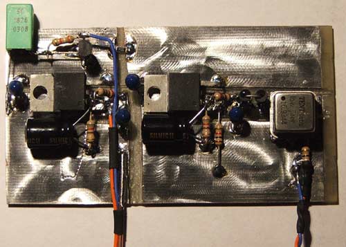 |
left: Here's one we made earlier, freehand. Two LM317-based regulators and a Tentlabs XO module. If fit looks a tad rough...well it's twice life size and was knocked out with a Dremel and good bottle of red... On the left is a reg set for 5v and used to power the DAC. On the right is the complete clock PSU and oscillator, with twisted pair connection of 0v return and clock signal. Less obvious is the capacitance multiplier used as a noise filter on the incoming supply, the two separate ground planes for each half, the decoupling of the raw supplies preceeding the regs, and the SMT decoupling components on the plane split under the clock. 10uF silmics increase PSRR for the LM317s, and tantalum caps decouple all inputs and outputs locally. You can also use the new clock to feed the transport decoder directly, rather than loading the dac buffer section with this task. Find OF12 next the ribbon cable bridge and remove the resistor immediately adjacent. connect a wire to the left end of OF12, taken back to a 390ohm resistor at the XO output. That's all! |
12 Find the two links from pins 15 and 17 of the LA9216 chip, these are R and L audio output. Carefully turn the player on and verify these two pins are within a few mV of 0v. If so, good, you can simply remove the output coupling caps (100uF/25v)and replace with wire links. After all , the best coupling cap is NO coupling cap.
A more drastic mod, but recommended: lift the wire links from pins 15 and 17; remove the two 470pF ceramic caps; link from pins 15 and 17 to L and R output directly using a resistor of 47-100ohms. This helps decouple the interconnect cable's capacitance from the output opamp, and bypasses the parts on the main PCB.
As standard the output from the 9216 stage passes through a 470ohm resistor, after which is a 470pF ceramic cap to ground, another 470ohm and two ferrite beads in series before connecting to the output socket. This is all to do with reducing RF noise susceptibility on the output for EMC compliance. However, it also raises the O/P impedance to nearly 1kohm and has a large part to play in the limp, strangled and slightly coarse sound of the stock Planet. You can lose the lot! A check with an o'scope showed that output spuriae aren't affected by losing the standard arrangement, so don't worry about it.
13 Have a coffee, check your soldering afterward. When planning mods like nos.7 and 11 be mindful there isn't actually much headroom inside the Planet's case over the analogue stage to fit in extras, so you may need to trial-fit before final connections are hardwired.
So, in summary:
Reclocking with external oscillator:
Clock mod to decoder:
14 Refit the ribbon - push it firmly into the PCB connector; reseat the case halves and tighten the bolts.
Now set the player up, plug in and enjoy!
*Jan 06 update: get slightlymore of the same by finding the two 10K resistors that link the output from the DAC to the analogue stage and replace with 12kohm parts. The penalty is an paltry 0.5dB reduction in gain (which you won't notice) with a reduction in noise (which you will). This first analogue amplification stage is an inverting opamp with all the gain to bring the signal up to output levels, a noisy way of doing things. The slight increase in the R value alters the gain structure enough to reduce the noise gain quite noticeably. It also drops the first lowpass -3dB point from 106Khz to 88Khz, never a bad thing since it helps keep HF noise out of the linear amps. BTW this has no effect on the overall Bessel alignment of the output filter, which has remarkably constant group delay over the whole audioband (from simulation).
© the twisted pair 2005