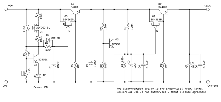
The low pass filter cleans the mains noise, and noise generated during the AC rectification process. The ripple at the output of the rectification bridge and smoothing capacitors has a saw-tooth form and can reach, depending on the quality of the capacitors and the load, tens to hundreds of mV. This ripple translates into noise at all audio frequencies and above, causing coloration and lose of details. The low pass filter stage reduces this noise to a very low level.
The SuperTeddyReg was designed to allow positive and negative versions using the same PCB.
The graphs below compares the noise level at the output of the rectifier, after the first stage, and at the SuperTeddyReg output.
The circuit

The regulator stage
The regulator stage consists of a current source and a bipolar transistor configured as a voltage reference (acting like a Zener). Unlike the TeddyReg, the SuperTeddyReg is no longer using a the LM317 for the regulator stage. Although it provides a good level of voltage regulation, the LM317 is very noisy, and event the following filter stage is unable to completely filter this noise.
The Current Source
Q1 and R1 act as current source (for the positive version Lnk1 should be positioned at the "+" position. Use R1+ and a link instead of R1-). With a 2SK363GR and 100R the current is around 1.5-2mA.
The Voltage Reference
Q2, D1, R2, and R3 act as voltage reference. I have tried various configurations, and found that zeners are extremely noisy, even monolithic voltage references and shunt regulators such as the LM329 were too noisy.
The voltage at the base of Q2 is about 2.42V, which means that about 0.57mA flows through R3 (when set to 4.2K). The voltage on the Collector of Q2 is equal to the Vb + Ir3 x R2. Using 42K for R2 we get 2.4 + 0.00057x42000 equals around 27V. In practice the voltage varies and a 10K trimmer is recommended for fine tuning.
Comparing to a Zener diode or monolithic voltage references, a transistor based voltage reference has high output impedance, but since there is no current through the gate of Q3 the output impedence has no effect in this circuit. On the other hand this voltage reference has a significantly lower noise level which is much more important in this context.
The voltage reference is followed by a first order low pass filter gyrator that cleans part of the ripple. R6 is a bias resistor, it should be set to allow 1-3mA through Q3. The purpose of this resistor is to force Q3 into its linear region where it performs better.
The filter stage
The filter stage is similar to the TeddyReg filter stage. R7, R9, C3, and C4 act as 2nd order low pass filter, and Q6 and Q7 act as Gyrator.
R7 and R8 make a voltage divider and should be calculated to allow a minimal dropout of 2V on the filter stage. The negative Vgs of Q6 is approximately equal to the positive Vbe of Q7, which means that the output voltage is approximately the same as the voltage of the voltage divider.
R7a, R8a, and Q5 are optional and act as accelerator, that is, they charge C3 rapidly and disconnect as soon as C3 reaches the final voltage defined by R7 and R8. The accelerator circuit is required when powering DACs, clocks, and other CD circuits where start time is critical. Note that R4 and C1 cause a delay too, smaller capacitor and resistor (3.3uF, 10K) values are recommended for start time critical applications.
Short circuit protection
A 2SK117GR has a current limit of about 10mA, and the D44H11 has a hfe of about 200, the combination of the two allows a maximum current of around 2A. The D44H11 can withstand up to 10A and 50W so in practice the circuit is protected against short circuits at the output (I have tried it...). Note however that using jfets with higher Idss will allow higher currents.
Negative version
The SuperTeddyReg PCB was designed to allow implementation of either positive or negative version on the same PCB. For the negative version:
- Use a wire link instead of R1+
- Use a wire link in the "-" position of Lnk1
- Reverse the polarity of all electrolytic and Tantalum capacitors
- Reverse the LED polarity
- Use P channel jfet for Q3 and Q6 (e.g. Toshiba J74). For symmetric pos/neg regulators use 2SK170 for the positive regulator instead of 2SK117
- Use BC560C for Q2
- Use D45H11 for Q4 and Q7
- Use BC560 for Q5
Sound Quality
The sound of the SuperTeddyReg is better than the TeddyReg, and better than anything else I have tried so far (I keep saying so with every new version...). The improvement is not huge but clearly perceptible. The effect it all over the spectrum but, as could be expected from the measurements, especially in low and mid low frequencies. Piano has more presence and sounds more natural, drums have even more punch and dynamics, and everything is more focused and involving.
The SuperTeddyReg design is the property of Teddy Pardo and is published for non-commercial use only. SuperTeddyReg PCBs and ready built modules can be ordered at www.teddypardo.com