Inveterate meddling #376: (very) alternative PSU arrangements for Naim preamps
This is simply an abridgement of this PFM forum thread, the page contents being generously contributed by Mr. Tibbs. If preferred, the whole discussion - less pictures - can be read as a single html file cached here (archived to 30 Sept 06.)
27-10-05, 01:24 PM [A previous thread] put forward the notion that you can only get so far with super-supplies and regulation. The other half of the supply (the 0V return half) needs at least as much attention, if significant progress is to be made. Ultra-low impedance 0V power supply to pre amp links were tried, followed by the split 0V rails. I think it's safe to say that anyone who's tried the split 0V mod and those who have gone further using multiple transformers with multiple 0V returns, would agree that there is much performance to be gained by looking at this area.
Lately I've been thinking that something more radical needs to be tried- something that may actually provide the ultimate 0V return path - no path at all! So, how can this be done? Simple. Let me introduce to you this most wonderful of creations, the DC-DC converter.
Put simply, this device is a miniature switch-mode power supply. It takes in DC, chops it up at high frequency, and passes it through a tiny isolating transformer, finally rectifying (and usually regulating) it back to DC. The bit we're interested in is the fact that it completely isolates both legs of the input DC, from the output DC. This means that if the device is placed close to the star 0V point in the pre-amp, the output -Ve can be directly linked to this point, creating the ideal 0V point. This is the ideal power supply scenario - where the power supply 0V and pre-amp 0V are one and the same. It's the equivalent of having the whole power supply right inside the pre-amp.
There are other benefits too. As these devices regenerate DC, they are pretty much immune to the quality of supply feeding them. No need for a Hicap or better, just a simple linear supply will do nicely. Something like a single rail Snaps would be ideal. Also, poor mains quality will not be an issue.
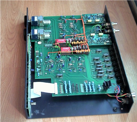
In my [Naim] NAC102, I've fitted two converters, one per channel of line stages. Each converter feeds the existing three local 1086 reg's per channel. The model of converter I've used is the Traco Ten 5-2423. It can operate over a range of IP voltage, and outputs +/- 15V, though I simply take 30V from across the outer legs to power the 1086's. The primary 24V supply I've used is a simple one - probably more basic than a Snaps. The important thing to note here, is that the 0V of the primary supply must be taken directly to the converters, and not connected to the pre-amp in any way.
This arrangement has made redundant a heavily modified Hicap, fitted out with six SR's and split 0V.
How does it sound? Really, shockingly good. Everything about the music is better. There is an obvious extra layer of detail, with instruments and voices sounder purer and more 'real'. The dynamics are bolder from top to bottom, with cymbals sounding clear and sharp and kick drum being felt firmly in the chest as well as the ears. Every piece of music I've played has struck me as being better emotionally portrayed, than I've heard before - so it's not just a 'HiFi' thing.
I can't recommend enough that you give this a try. It requires you to leave aside some well established ideas about what makes for a good power supply, but keep an open mind and give it a go.
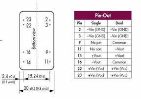
27-10-05, 05:04 PM Mus commented: 'That's very interesting, would you be kind enough elaborate on how you have wired the converter up. I have attached a picture from the spec sheet to help.'
|
Input from the supply:
|
Considerations:
27-10-05, 09:49 PM Switched mode supplies are relatively noisy! They generate up to 50mV p-p, at the switching frequency (300kHz), and with harmonics. They spew out this noise in all directions. A simple regulated primary supply should stop the noise getting as far as the mains. On the output side, a stage of regulation should keep the noise from potentially de-stabilising the amp stage you are trying to feed. If you are not using a reg after the converter, a simple LC damping filter should be used in addition to the existing Naim RC filter. The type of converter I use has a shielded metal case - I would not risk the plastic covered type.
Additional decoupling:
31-10-05, 09:25 PM Late yesterday I got a spare half hour and rummaged through my parts box. A couple of 370uH inductors were found. These were inserted into the output +Ve of each converter, with a 22uF tant directly across the converter output, and another tant after the inductor, to form a CLC filter (the inputs of each local 1086 also have a 22uF tant to ground).
The whole thing was left to simmer until I got home from work today. A few records later, I'm almost certain there is no difference with the filters in place. A result then, as I half expected them to actually make the amp sound less good ;)
|
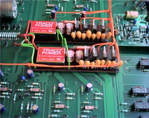
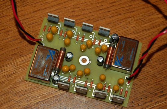
To the right of the converters, you can see two 100uF cap's and beyond those the 470uH inductor. These form the CLC filter on the output of the converters. After that comes the bank of four LT1086s. The row of Tants in front of those are 22uF - used on the output and adjust pins of each regulator. In among the tants you can just about see the two resistors per reg. A bit fiddly to build up, but the boards had to be kept small enough to fit on either side of the preamp 0V point. You can take the converter outputs direct to the local reg's. I have tested with a cap/inductor/cap on the output of the converters but can detect no difference in sound - though it's probably still wise to include this. Use an inductor on the +V ouput rail only, not the -V. The caps go across the output, one before and one after the inductor. The 0V reference for the internal regs should be taken to the preamp 0V point as normal. If the local reg's are sited away from the converters, make sure you place a small cap across the input of each local 1086 (a 22uF tant is good here). The converter output pins are; -V pin 11. +V pin 14. Again, there is more info on this earlier in the thread. |
08-12-05, 05:52 PM Here is the basic circuit showing a DC converter, supply input, supply output to local reg's, and CLC filter. When I get some time I'll do another to show the circuit for 1086's. Don't forget, the primary supply input to the converters MUST go direct to the converters and have no other connection to the preamp. Choose a power inductor that is rated at 300mA or greater:
Try two converters in the preamp first, before starting in the XO. One simple outboard supply (like the type you have) will feed both converters. The input from the external supply should connect straight to the converters; -V pins 2&3. +V pins 22&23. If you have a 102, you should power the control circuitry with a separate linear supply.
26-11-05, 02:22 PMUpdate: I've now tried out a couple of alternative primary supplies, leaving each in for a few days to give a good feel for any change. Interestingly, the results do change with changes in the primary supply, but much less so than is normally the case with 'standard' regulation. I started off by feeding the two converters with a single rail supply that is close in spec to a Snaps. As already posted, the results are excellent- comfortably better in all areas than a Hicap with six SR's.
Next up, came a ratty wall-wart that was just about able to deliver the 8W that the two converters demand. The sound took a bit of a nosedive, with the bass definitely not as well defined, and a certain loss of clarity in the mid-band.
Lastly, after the plain 317 reg's were re-installed in the Hicap, I hooked a single rail of it up to the converters. This is giving the best results yet, with the preamp sending out a signal with a real 'master tape' feel to it. The other half of the Hicap is being used to power the preamp control circuitry, but I suppose it might be worth putting the wall-wart back on control circuit duties, to free up the second Hicap supply. This would give one Hicap supply per DC converter.
That said, I could very happily live with the sound I'm getting now. It's obvious that the music signal is passing through the preamp with the absolute minimum of degradation which is a pretty tall order for a complex bandwidth limiting design.
Traps for the unwary
01-01-06, 08:42 PM We've identified the main problem of strange noises when using the remote volume and balance controls. It's a small mistake anyone could make [and] really a NAC102 specific problem, which stems from the fact that the 102 needs some form of external power supply to drive the control circuits. [so note - this advice will also apply to NAC82 and NAC52..! - mc] Jo had used the output of one of the converters to power the control stuff, the problem here being that as soon as he operated the remote volume control, the (substantial) extra current demand of the motor was probably enough to overload the converter, making it object accordingly! That aside, the control circuits are continually noisy and this would no doubt be pulling down the performance of the converter driving them, affecting the local reg's and therefore the signal circuits being fed by the same converter.
There are at least two options to get round this problem. The easiest is probably to build a small separate conventional NAPSC type supply and use it to power the control circuits in the usual manner. What I did was to use half of my split (electrically separate) 0V Hicap to power the Traco's, and the other half to power the control stuff. There is another possible option, but it involves the use of a third DC converter in the preamp, and I don't want to go into detail about it until I've proved it works properly.
Using a separate (NAPSC or half of a split 0V hicap) supply for the control circuits means that the external 0V of the separate supply will be common to the preamp 0V point, but this will have no impact on what the converters are trying to achieve in isolating the main power supply from the preamp signal circuits. The converters are still able to make the preamp perform as if it has no external cable link to an outboard supply. Remember that simply connecting up some sources (CD, Tape, VCR etc) means that the ground of these sources is tied to the preamp 0V point, but they shouldn't interfere with the function of the signal circuits - whether fed by a conventional outboard supply or internal DC converters.
Feedback:
28-09-06, 06:29 AM 'mike_in_co' in posted: "Just a few hours ago I installed a board similar to what the illustrious Mr.Tibbs installed in his NAC102. My pre is a 32, and it's a single board with two SMPS modules (Wall Industries, similar in spec/performance to a Traco), and 8 LM317ATs. The board size was 2.5 x 3.6 and fits snugly in the space between the tape buffer cards and input buffer cards (just behind where the balance pot would be). I also did the 0v mod that moves the star point to the preamp at the same time.
My listening has been only at low levels thus far, and only digital (squeezbox 3). Even in this short, somewhat compromised listening situation, I can hear why he was so enthusiastic. Instantly noticed more dynamic variation and expression, more air and life, and a sense of ease and flow across the entire spectrum. All of this at a level that won't wake the rest of the family. Even at the low volume I could hear and feel bass note thumps and rumbles. Very eager to get the volume up a little more and let things run in. More reviews as I get time to listen.
I also have a pic of the board just before installing into the pre, which I'll try to post somewhere and link in. Mr Tibbs, a huge thanks for this wonderful idea/inspiration!"
28-09-06, 05:23 PM 'mike_in_co' in posted: I've had more time to listen, and at louder volumes. Short version: this change has brought more musical improvement and expression to my system than anything I've done before. Alive, expressive, engaging, human. Sonically, there's gobs more of everything and it's in the context of music, not sound. Mr Tibbs used the phrase "master tape" I believe to describe the sound, and that is a good way to put it. Feels like very little is between you and the intent of the performers and the piece of music.
I previously built a 6 x LM317 external PSU with separate lines to each card, and later a 2 x ALWSR SNAPS, both of which were steps up. This change is in a completely different league. I don't know that it's the SMPS specifically. It could be moving the regulation to within inches of the boards, or relocating the 0v to inside the pre, or the sum of those and the SMPS board that makes such a dramatic change. Whatever it is, just 12 hours in I have much more of a musical experience coming out of my system than before, and certainly more than I expected ... Can't recommend it enough"
Links:
© 2005, 2006 Davy Stewart (aka Mr Tibbs) & members of the Pink Fish Media web forum
www.acoustica.org.uk (opens new window)