For availability of high-quality PCBs for this project, please watch the front page
Now, back to our scheduled programme..:
Inveterate meddling #107: a fleapower wideband regulator

This is a deceptively simple, high performance voltage regulator based on the obseration that for very light loads the error amplifier itself can source all the current you actually need. All it takes is a simple voltage reference, and a very high performance opamp.
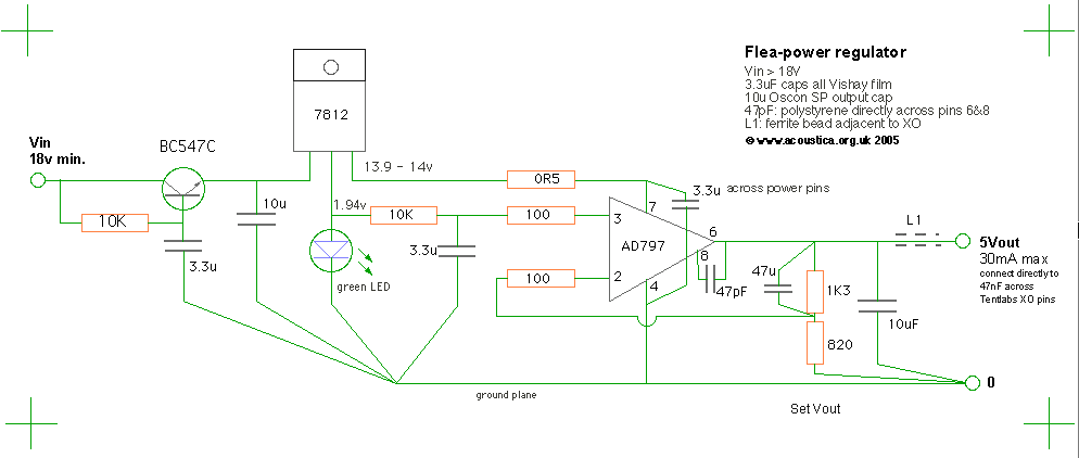
Starting on the left of the diagram, input is supplied from a very simple PSU or any existing suitable voltage rail. I used a rather small centre-tapped transformer/fullwave rectifier/1000uF - the only wrinkle being a 60uH/0.4ohm choke (from the bits box) before the 1000uF electrolytc which completely kills the reverse recovery spike from the cheap diodes. All remaining garbage is swept up by the simple capacitance multiplier at the input (more information on exactly why this approach is used can be found here.)
Next comes a conventional three-pin regulator which provides a stable, low impedance supply to the circuit. I've taken advantage that the reference leg is basically the output of an internal current source by using this to drive our voltage reference - a plainjane green LED. Of course you could use a proper LM329 or similar, but actually LEDs do a pretty good job; just 6-8uV of noise over the whole audio bandwidth is typical. LEDs are not temperature compensated, and as a result the voltage will drift at -2mV/degC - which really doesn't matter in this application. In any case the reg will live constantly powered-up inside the cd player and so it's not exposed to rapid temperature fluctuations. As to which LED to choose - blue LEDs have a forward voltage of c.3-3.6v but seem to have higher dynamic impedance and noise. I used a plainjane green LED, which gives about 1.94v, subsequently well-filtered by the 10k/3.3uF filter. The 3.3uF caps are film types to avoid adding leakage noise.
The weapon of choice for the amplifier is the extraordinary, low-noise AD797. This is both a very fast and very low noise device, with a slightly unusual architecture. As such it requires some care in implementation to get the best out of it in terms of regulator performance - and stability.
First key issue is decoupling the opamp. This should be applied right at pins 4 & 7. Note in the schematic at the top of the page the opamp is supplied via a 0.5ohm resistor; this does double duty, stopping the 7812 oscillating with the film cap on its output, and providing a convenient place to monitor current draw (more on this below).
Low impedance sources to the inputs are key to getting the best noise performance from the '797; in this circuit these impedances are dominated by the 3.3uF filter and 47uF feedback caps, which both appear as short circuits over most of the spectrum. Since we have some very low impedances seen by the inputs to the opamp I've included 100ohm input resistors to the AD797 inputs (pins 2, 3). These have a negligible effect on noise but provide damping which helps stability in this non-inverting configuration with gain >1. See page 10 of the AD797 datasheet for a detailed explanation (linked at the bottom of this page).
The two resistors at the opamp output are the feedback divider and set the opamp gain, and hence the output voltage. Here, the ratio is [(1300/820)+1] = 2.58x . With a 1.94v reference we get 5.0v output; using two forward-biased diodes (0.65v x 2) instead of the LED would give about 3.4v output, ideal for 3.3v systems in SACD players. Alternatively, keeping the LED and using a 1Kohm, multi-turn potentiometer to vary the feedback would be a good alternative if adjustability is required. The 47uF capacitor rolls off noise-gain and is recommended. In fact anything of 1uF or over is good here - I use a small 1uF film cap.

|
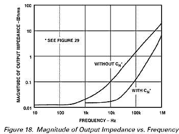
Finally the novel internal layout of the AD797 gives one major advantage. Between pins 6 and 8 we can connect a small capcitor (47pF) which closes an internal feedback loop and has the effect of reducing distortion by reducing output impedance dramatically at high frequency; now that's of interest for a high performance regulator! This wrinkle is explained in the AD797 datasheet, see figures 18 and 29 in particular.
The upshot is illustrated in the graph, left - impedance is held low a whole extra decade over the uncompensated circuit! As a point of reference, this little reg performs better out well past 100Khz than an LM317 can manage at just 1Khz... |
Such speed and low impedance (=lack of damping) requires a bit of care in application, and so following the feedback network I've shown a 10uF output capacitor. In this circuit it is essential with the AD797, the opamp will oscillate without - slightly unusual when opamps usually hate capacitance on the output. The value can be quite small, if you wish to experiment I'd recommend 2.2uF minimum. Low ESR isn't wanted; a 10uF tantalum is ideal and virtually guarantees stability, especially if you add a 1ohm resistor in series with it to add a touch of damping. Best measurements driving a clock module come from having an additional 47-100nF SMT ceramic right at the Tentlabs XO also; with one there's nothing I can see on the scope except just 2mV of ripple at the clock frequency. The ferrite bead helps with EMI control; as an alternative you can wind a simple inductor - 20 turns of wire in a single coil about 4-6mm diameter. Ensure you connect a 1ohm resistor in parallel (between the ends of the coil); it will damp any tendency for the coil to 'ring' with load capacitances.
With a Tentlab XO running on the output the whole thing draws about 18-20mA. The opamp itself draws about 10-12mA, added to which will be your load current. Calculating the current drawn (by measuring voltage across the 0.5ohm resistor) is an easy way to check if you don't have an ocilloscope - if the circuit seems to be drawing significantly more than it should then it's highly likely the 797 is oscillating at HF.
For a dirty-cheap version this circuit also works very well with an NE5534 (or any other low-noise opamp), just leave out the 47pF cap - and the 100ohm resistors also if desired.
Note: The amount of current this AD797 regulator can provide is limited by dissipation - with the 14v rail, 50mA is the maximum the 8pin DIP will tolerate, although in principle the 797 can easily deliver more. To keep thermal effects down and maintain accuracy, 20mA is recommended as a practical maximum - far more than enough for a Tentlabs XO, or the analogue stages of a bitstream DAC etc. For a bit more, read page two...
On to Part Two...
Misc. reference information:
© the twisted pair 2005