Naim Power Amps: mods and upgrades
this page and links generously contributed by Ced Taylor, Jan 2009: www.acoustica.org.uk (opens new window)
| Poweramps: Mods and Upgrades |
| The following is a list of mods compiled from around the internet, principally contributors to pink fish media, neil mcbride and avondale audio. |
| All comments and opinions are mine. They are meant as guidelines only and other opinions, information and experiences are gratefully received (contact details below). Saying that, something is probably very wrong if you're getting no joy out of the mods. |
| None of the information below is in anyway an endorsement of the modifications involved and no responsibilty can be taken for any consequences whatsoever of attempting them. Check parts against datasheets and schematics also to be safe- I have made more than one typo in my life. Best know what you're doing before trying them as power amps are particularly merciless with feck-ups and dodgy soldering etc. No nice DC blocking caps and low currents to save your equipment and self. Basically you take responsibility for your own actions comrades so use a bit of judgement. Cheers, Ced. |
| Naim Amplifiers | |
|
|
|
| Nap 160 | Nap 250 | Nap 135 | Nap140 psu |
 |
 |
 |
 |
|
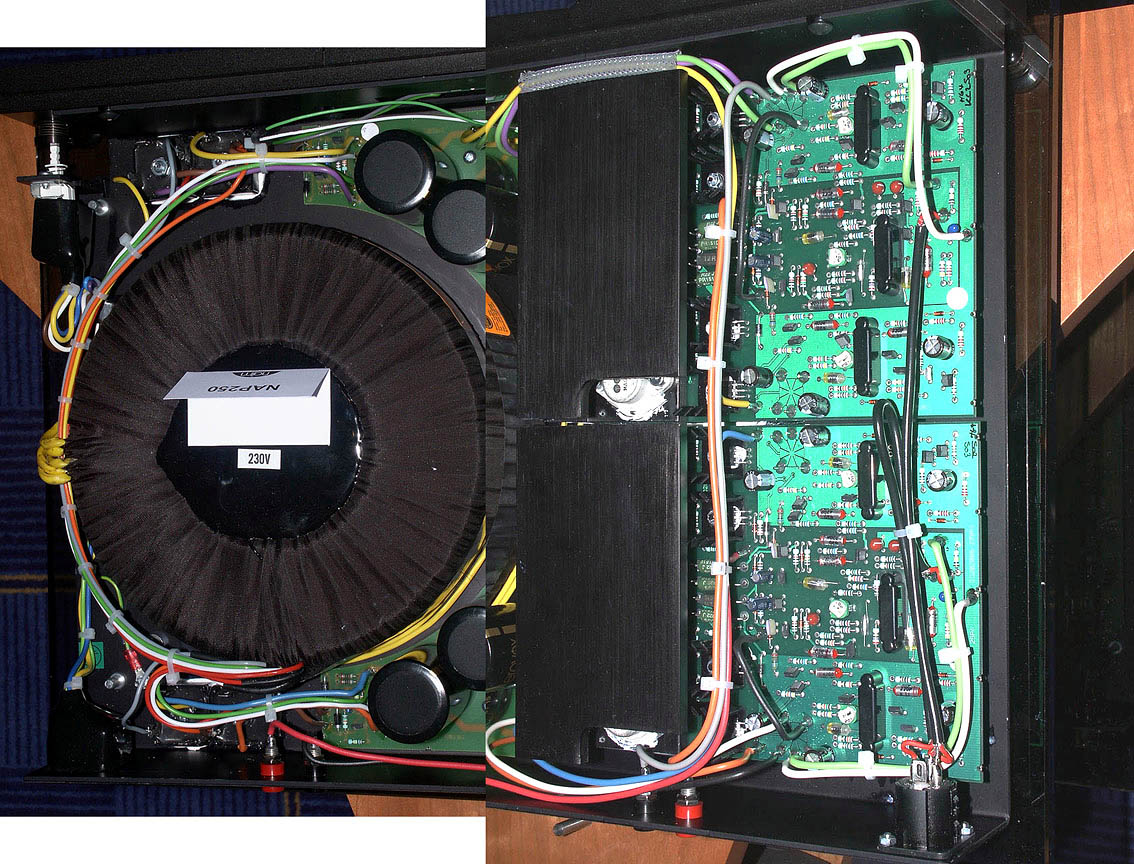
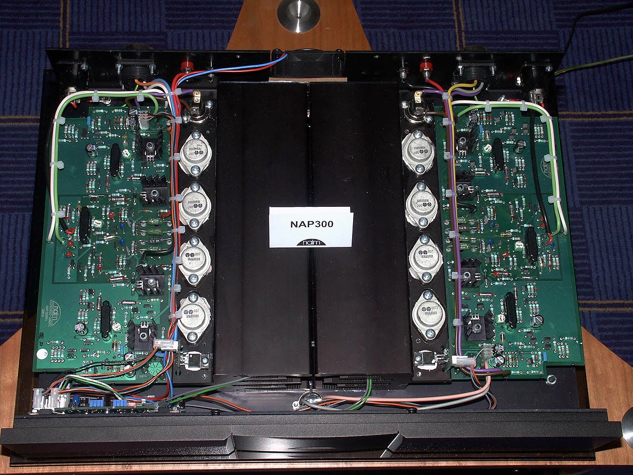
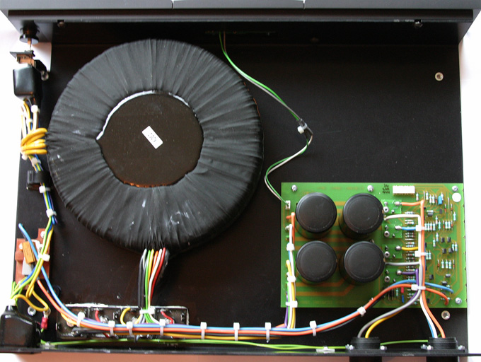
| Nap 250-2 (composite pic) | Nap 300 amp | Nap 300 psu | Nap500 amp |
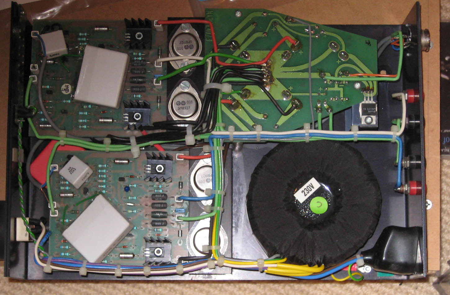
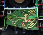
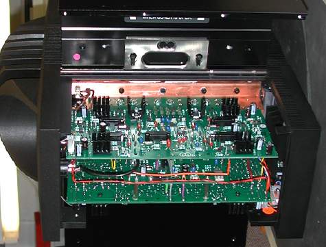
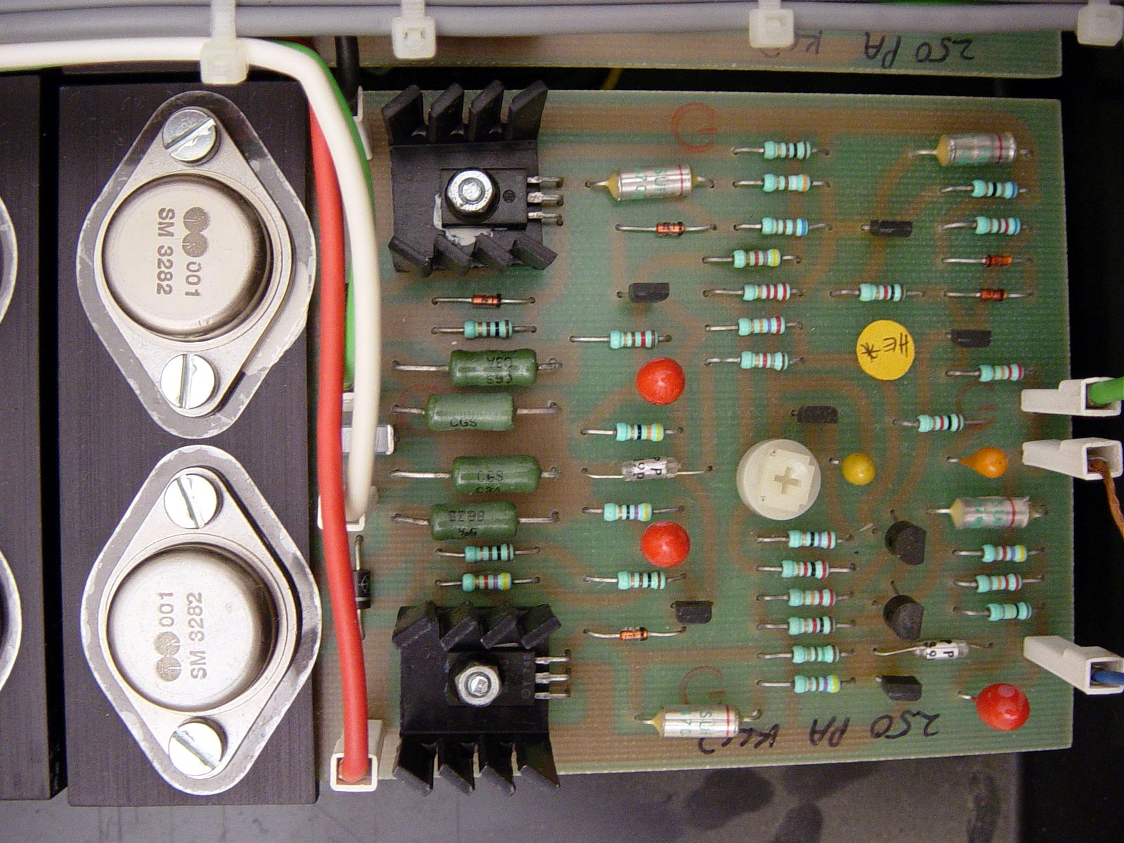
| amp boards (nap250) | 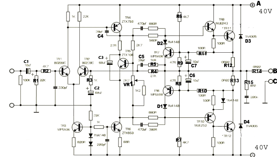 |
 |
 |
 |
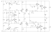
| Original
series Amp schematic (fig 1) |
Nap
250/135 amp board with overcurrent protection removed (fig 2) |
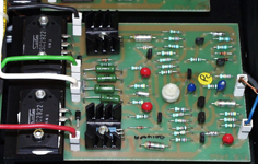
Chrome bumper Nap 140 amp board with Sanken output transistors (fig 3) | Nap
250/135 amp board pic (fig 4) |
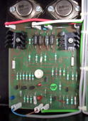
| Regulator boards (Nap 250) | 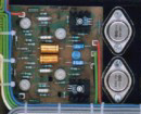 |
 |
| Nap 250 regulator board(fig5) | regulator schematic (fig 6) |
| other mods | ||
 |
 |
|
| output transistor decoupling (fig 8) | output transistor decoupling schematic (fig 9) | |
| circuit descriptions | |
|
Amp descriptions:
|
The essential amp circuit remains the same for all Naim poweramps for a series though there are the original and the '500' versions. The orignal versions cover the chrome bumper and olive fascia series. The 500 version boards are in the brushed aluminium fascia series. For
original models, the essential difference between a Nap140
and
a
Nap
135 is in the
quality
of the
power supply and the power delivery. For
new 500 series models, the difference I believe (and I may be wrong),
between the lower Naps and a Nap 500 is still in the quality of the
power
supply
and
the
power
delivery. The 500 has comparatively much more sophisticated
power supplies and is a bridged topology [using 2x modified NAP ciruits on each channel- MC]. |
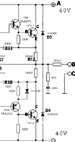
| Regulator board descriptions | Pretty
simple discreet power opamp design and essentially very crude-
fig 6. Based on an old old design by Anthony Holton if an old schematic
and notes don't deceive me. Doesn't take much to jazz this up e.g.
decent
current
source
at the base
of the long
tailed
pair, decent voltage reference, filtering and internal regulation
etc. This was done by someone a few years back (current source anyway)
who
made favourable comments of the results. Reports
are
generally
that
the
regulator
is responsible for the slightly 'darker' and more detailed sound
of the old 250 upwards but also damped the dynamics somewhat? It
also has
current
limiting
circuitry which puts a fat bit of impedance
(0.1ohms) on the power rails and is generally not a good idea sound
wise imo, which might have been responsible. Also its apparently
a bit of a noisy bugger so not that great performance though it probably
cleans
up
the rails
a tad.
[NB the 0.1 ohm series resistor is inside the feedback loop, so pretty insignificant as a component of dynamic output impedance in this regulator design - MC]
Historic rumours
would indicate the regulator boards were a good way of implementing
current limiting in what was essentially a studio design and needed
to be, above all, rugged to abuse by hairy muso types used to absentmindedly
sticking anything anwhere while fussing over faders and 'the top
end, Jerry'. And indeed old
reports
were that the 180 is a tad more dynamic than a 250. I've had or audititoned
all 3, and for my money would stick with a 140 and mod that if it
can drive your speakers happily. As stands I found bugger all worth
dropping a grand+ extra over between the three.
[For a more recent discussion of the NAP regulator design and some modification ideas, please see this recent Pink Fish media thread - MC, 23.01.09]
|
| Mod | Comments and information | Bang for buck | |||
| Basic Mods- Amp boards | These are all reasonably simpl | ||||
| 1 | upgrade input cap | upgrade
C1 form blue 10uf tant to a 1uf-3.3uf Evox SMR polyphynl sulphide
capacitor. Other caps are also viable- see preamp coupling caps section. |
1uf
SMRs will technically give a very slight bass rolloff but are easy
to fit. the rolloff is not audible. Oh no. 3.3uf is nice
but must be fitted with flying leads. 10uf doesn't harm either but not
necessary. |
5/10 | |
| 2 | Remove protection circuitry | Remove the following components: R6-R11, C6-C7, D1-D2, TR7-TR8. |
See
fig 3. This removes the overcurrent protection circuitry which apparently
significantly
muddies the sound. Haven't evaluated this mod on its own but
together with mods 1,2 and 3, 4 (electrolytics) it makes a definite
improvement. The macbride and avondale versions of the Naim amp board
do not have
this
protection circuitry either and its efficacy is considered suspect as
its main purpose is to protect the output devices from overload.
Worth
bearing in mind is that the new 500 series amps have much lighter protection
too. Neil McBride says:"Without
it, the amps are more powerful sounding, more transparent, and more involving
and musical." I
agree. Easy and reversible (with a dab of solder) is just to snip
one leg of D1, D2, R6, R7 and R10, R11 if you fancy being a bodger. |
5/10 | |
| 3 | Upgrade feedback cap | Upgrade
c2 (red tantalum cap)
In
the Nap140 this is 47uf, in the macbride and avondale NC200 it is 68uf
and in NAP 250s it is also 68 or 100uf . Voltage rating must be 6V
or higher,
generally higher rated caps sound better. |
Now
Ive done this with an elna silmic of the same value as a nice drop
in replacement. It makes
a nice little upgrade. |
11/10 | |
| 4 | upgrade VBE biasing decoupling cap | Replace
c3 (usually the red tantalum cap) with better of the same value. Les
W at avondale also recommends a 68uf BC128 solid aluminium cap. In the
Nap140 this is 47uf, in the macbride and avondale nc220 it is 68uf
and in NAP 250s
it is also 68. Voltage rating should be 16V or higher, generally higher
rated caps are better. |
not been evaluated independently but it would be rude not to do this while you're at it. I've used an oscon and now run a 47uf evox MMK. You'll need flying leads. I think anything above 10uf is considered good so try in the 10-68uf range- it basically irons out voltage variation in the biasing VBE. | ? | |
| 5 | upgrade direct signal path and feedback loop resistors | These
are R1-R5 on fig1. Replace with vishay dale RN 60 or Welwyn RC55y
or higher grade resistors. See 'Preamp
feedback loop resistor' section for alternative components |
Not
been evaluated in A/B comparision, but it didn't do any damage for sure.
|
? | |
| 6 | upgrade power resistors | Replace the power resistors R12-15, (fig 1) with Caddock MP930s. | Not
been evaluated in A/B comparision,
but it didn't do any damage for sure.
|
? | |
| 7 | output transistor decoupling caps | decouple
both+ve and -ve powerrails on each board with the highest possible
quality
caps (eg Rubycon ZL) 470uf, 50V (see fig 8) right
next to the output power transistors.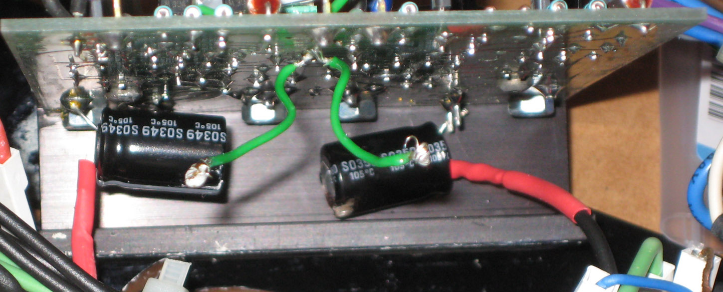 Fig11. Rubycon ZLs soldered to output transistors under the boards. (Green wires are where an Evox MMk was removed so you can see). Note on the picture in mod 3, the 4 extra black wires going to star ground for the ZLs. |
See
fig 8 and 9. This was another big mod. I loved it. Just added more
power, authority, attack etc blah, imaging, highs, lows whatever. solder
capacitors C10 and C11 in fig8 to the correct pin of the output
transistors under
the boards (solder to the actual pins as the caps must be as close to
the transistor as possible) and run flying leads back to the star
earth
between the main psu reservoir capacitors NOT a 0V point on the actual
amp boards. Use at least 1mm2 wire for the OV return wires for a
good
low impedance connection. You only need to use 2 leads as per fig9 as,
as Martin says, 'there is no interaction between pairs of caps sharing
a return to the main 0v star point - this is a ClassB amp, so only one
half of the output stage conducts (and needs decoupling) at a time
under
load. Either
way results are an immediately noticeable increase in 'slam' and
weight
and a general tidying up of the sound- everything just sounds more lifelike. |
8/10 | |
So
with these mods you will have given yourself a new poweramp that I
would confidently expect to trounce a 250-2/300 in most respects
for a few quid and a bit of time. Your poweramp must be able to drive your speakers.
If its underpowered no amount of fiddling will compensate the lack
of drive power. A 140 with EPOS 22s for example sucks like a hoover
whatever
you
do.
|
|||||
| Mod | Comments and information | Bang for buck | |||
| More advanced Builds | |||||
| 1 | Build your own | Build the Avondale AZ260 amp |
This
is based on the the Naim amp circuit but more refined; with upgraded
components, tweaked power rails, no output protection circuitry and
some other circuit tweaks such as emitter degeneration on the input
pair and onboard output inductor- Avondale's NC200 poweramp boards.
Giving apparently a much more powerful, refined
and
musical
performance
. Avondale
also supply an apparently excellent CAP6 reservoir capacitor board,
and some very good low impendance toroid transformers. Not heard
one, but all those people can't be wrong- theres been pretty universal
praise for them. |
? All reports are highly favourable compared to Nap250/Nap135s | |
| 2 | Builda Neil McBride NAP Clone | Build
a macBride 250/135 clone |
Based closely on the nap250/Nap135 with a few refinements such as upgraded components and eliminating the overcurrent protection circuitry on the amp board. It runs with power regulator boards. Is it worthwhile going down this route? Yes, as a spring board if you want to DIY heavily, have plans for a very personal modified creation and will end up rebuilding it and ripping it apart serveral times, need a particular chassis layout, wish to try a NAP300 chassis arrangement etc. Basically i'd look at it as more a recipe idea whereas the avondale is a ready meal. Either way check Neil's website here as its still a very useful site even after all these years. Just looked again and its all getting very self referential around here now, heh.
|
? | |
| One can go further than the above mods to an existing amp but the law of diminishing returns kicks in powerfully (well, sort of) and you really have to build from scratch with plenty of space and a lot of time to try things out. Think of a poweramp as essentially a high voltage preamp with a high current output buffer stuck on the end and you won't go far wrong. | |||||
| Mod | Comments and information | approx cost | Bang for buck | ||
| Minor Mods/Servicing | These are all reasonably simpl | ||||
| 1 | Adjusting the output DC offset |
Les
W of Avondale has said: "for those who are looking for the
offset adjustment on Naim amps, there isn't any. The offset is determined
during manufacture
by the gain relationship of the two transistors forming the VAS (Voltage
Amplifier Stage) [TR1 & TR2 on fig 1] at the input of the amplifier.
Bench selection of these transistors during building assure the
offset
stays at a pre-determined level (10 - 30mV) during the life of the amp." ** measure
the voltage between points B & C in fig1 (the outputs)." |
? | ||
| 2 | Adjusting the bias (standing current) |
Make
sure no input nor speakers are connected to the poweramp. Personally
on my amp I solder a 10 ohm power resistor between the +ve psu supply and
the +ve power terminal of the amp board. its just a bit of extra insurance.
Aim for about 0.36V accross this
resistor. When
I'm there, desolder the resistor and resolder the supply direct to the amp
board. |
? | ||
| 3 | TR11 & TR12 OUTPUT TRANSISTORS |
These are TR11 & TR12 in fig1. Naim use custom NA001 transistors sourced from Semelab. However they are not deeply magical parts and alternatives are quite acceptable. Alternatives in TO3 cans that have been used as replacements are BUV20 at about £12 each and MJ15003 at £3. Both recommended by Les W. He states, and I paraphrase, that he considers the MJ15003 very very agile and informative but the BUV20s deliver the power and the glory. Neil mcBride recommends MJL3281a but these are T0264 flat packages and are only viable if building from scratch, probably using his boards. Not compared the three directly myself, Yet, but the MJLs are quite acceptable for sure. I wouldn't expect night and day differences in the grand scheme of things either way though. Old
NAP140s used to use Sanken 2SC2922 ouput transistors (see fig 3)
before
this was changed to the TO3 NA002 and NA001 transistors. still available,
just search the net. |
? | ||
| 4 | TR1 & TR2 INPUT PAIR | BC546 are fine here- High voltage variant of the BC550. They need to be matched to give an offset of up to 30mv. see avondale schematic for how to here. | ? | ||
| 5 | TR3 | BC546 are also fine here or MPSA06 have also been used. | ? | ||
| 6 | TR4 | ZTX753 | |||
| 7 | TR5 | 2N5551 | |||
| 8 |
TR6 |
ZTX653 | |||
| 9 |
TR7 DRIVER |
MJE15030 | |||
| 10 | TR8 DRIVER | MJE15031 | |||
| 11 | Reservoir caps | Kendeil
caps are VERY nice replacements for Nap 180 ,250, 135s or for use
in Mcbride amps . Get
from avondale, audiokit or a few other sources on the web. though
note they are large
so there
may
be
some
fiddling
and
ingenuity
involved in mounting. Alternatively try a cap6 board from Avondale
though not auditioned one myself. Reports are very good. |
|||
Wow! Thanks, Ced! - MC
If you have anything we can add to this page for the benefit of anyone interested, please contact Martin.
www.acoustica.org.uk (opens new window)