Naim power supplies: mods and upgrades
page and links generously contributed by Ced Taylor
| For where to find parts, order codes and rough prices, of components described here, please check on the components and suppliers pages. As usual you undertake any projects described on these pages completely at your own risk. |
| Preamp psus | |
|
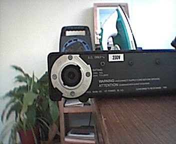
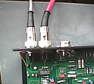
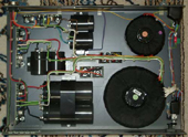
| Hicap (fig 1) | supercap (fig 2) |
| CD PSUss | 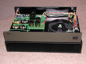 |
 |
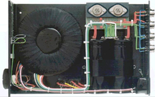
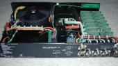
| XPS (fig 3) | CD PS (fig 4) | |
| PREAMP PSUs | ||||||||||||||||||||||||||||||||||||||||||||||||||||||||||||||||||||||||||||||||||||||||||||||||||||||||||||
|
Overview
|
The psus
on naim amps are always tempting to mod or diy as they appear simple but
are actually a bugger to get right . Its easy to spend hundreds on making
one that sounds no better than the powerrail off a Naim poweramp- I have
several toroids and dozens of regulators and reservoir caps to prove the
point.
|
|||||||||||||||||||||||||||||||||||||||||||||||||||||||||||||||||||||||||||||||||||||||||||||||||||||||||||
| Parts |
Obviously see the recommended components and suppliers pages for links and information on these parts TRANSFORMERS 2) you want at least 2 centertapped windings. In practice I have found seperate windings for analogue circuits give a major boost to sound quality (see the ultra preamp build notes on the preamp page) so have 2 as a minimum. You must have centertapped configuration too so that you can use half bridge rectification. This sounds better than full bridge rectification and I surmise this is because it avoids diodes in the ground line so giving low impedance to ground. Who knows though. 3) Beyond this it gets hazy. However useful key words if you intend to specify yourself would probably be: split bobbins, electrostatic shields, extremely low impedance secondaries, low core saturation, low capacitative coupling. To put things into perspective: I've tried several large toroids including a huge 630VA custom toroid from Antrim Transformers, all of which were completely blown away by a small 160VA twin centertapped R-core from Hi-Fi Tuning. Night and days stuff. RESERVOIR
CAPS RECTIFIERS REGULATORS
|
|||||||||||||||||||||||||||||||||||||||||||||||||||||||||||||||||||||||||||||||||||||||||||||||||||||||||||
| Build notes |
A couple of points to bear in mind are also: Low impedance- wiring: as regards the Julian Vereker comments above, keep impedance low by using low gauge hookup wire. I use 2.5mm2 stuff from maplins but probably anything 1.5mm2 upwards will be fine. You can even strip apart 3 core mains cable with these gauges from B&Q for example. Low impedance- connectors: Again regarding the Vereker comments, its worth noting that your DIN sockets have approx. 5mOhms impedance, Bundy sockets about 3mOhms and my preferred Neutriks also about 3mOhm. I would therefore solder the umbilical cord from the psu directly and use a cable gland so eliminating one socket. For comparison, 1m of 2.5mm2 copper wire will have an impedance of around 7mohms and a good reservoir cap around 8mohms ESR. Keep the rectifiers near the reservoir caps. There are big currents involved as the rectifiers switch on and off so keep them near the caps. There have been reports this makes a sonic difference and indeed some respected audio designers e.g. Jonathan Carr of connosieur audio mount the rectifiers directly on the reservoir caps with a pcb. The avondale Mcaps also use this principle. Earthing:
See simple mods 1 below. This is critical and can make a HUGE difference
to sound quality. Essentially the two supplies (+ve AND ground) should
be kept completely seperate and only joined at the star earth in the preamp,
not at the -ve terminals of the 2 reservoir caps. See the psu project
schematics below for a clear idea of this. Signal routing: See simple mods 2 below. Naim amps route the signal from poweramp to preamp via the pre psu. There are many reasons why this is technically illogical and listening backs this up. The solution is to route both psu and poweramp direct to the pre. This gives a shorter signal path and keeps power and signal lines seperate. In itself this gives a small difference though its not night and day but worth doing. However it allows you to use big cable for power umbilicals. This might also be useful:
|
|||||||||||||||||||||||||||||||||||||||||||||||||||||||||||||||||||||||||||||||||||||||||||||||||||||||||||
| SIMPLE MODS | approx cost | Bang for buck | ||
| 1 | The Mr Tibbs earthing mod |
This
is critical and makes a HUGE difference to sound quality with a far more
coherent and musical sound which just sucks you into the music in a wonderful
fashion. simply everything is better. Thanks to Mr Tibbs |
£0.20 | 11/10 |
| 2 |
Rerouting the signal path
|
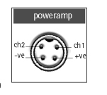
You can only do if you have an external PSU for the preamp. Use your 4 pin snaic to connect from preamp direct to poweramp. However you must desolder the +ve line on the din socket within the preamp (see poweramp din socket diagram below) as you don't want 24V coming into the preamp from the poweramp (if you use a nap90/140/150/160/180 etc). Then use your 5pin hicap snaic to connect directly between preamp and psu. See the avondale audio site for a diagram of this. However this then allows you to build an ALW power umbilical (see below) to transfer power which is nice. If you use 1mm 4 core you can then wire it up for the MR Tibbs earthing mod (no1) above with 2 +ve rails and 2 ground rails. Though I suspect using 2 of the 1.5mm 3 core cables with thicker gauges would sound much better.
|
||
| 3 |
upgrading the regulators
|
Replace the LM317s in your (DIY) hi-cap, flatcap, snaps etc. with ALW superregs. These are utterly brilliant and will transform just about anything they power. They are a bit costly in DIY terms and take a couple of hours or more to build but worth every single penny without doubt. The absolute must do. PCBs are purchased directly from ALW audio, see http://www.alw.audio.dsl.pipex.com/ For
Walt Jung orginal articles see see Low
Noise Power for Analog Circuits (ED Analog Special 6 23 1997) .
and also http://home.comcast.net/~walt-jung/wsb/PDFs/Improved_PN_Regs.pdf.
Note:
Remote sensing:
The superregs have both ground and output remote sensing facilities. To
be honest I'm not sure wether using remote sense make a huge amount of
difference. The main importance in this is to provide low impedance and
although significant, low impedance is not critical to good regulator
performance- the difference between suppling a premap with 27ohm powerrail
resistors and without is clearly to be heard and positive but not huge. Alternatives which have had good reviews are the Avondale tracking regulators and the Avondale APX boards. Not tried them personally but a report is they have a different presentation to the ALW superregs though are also good.
|
~£30 each | 10/10 |
| 4 |
DIY rectifier bridges
|
Bearing in mind comments regarding rectifiers above, here are pdfs for etching your own shottky full and half bridges. The diodes these are designed for are MBR20200CT. The bridges are designed to work to 20A, 200V. Parts available from farnell; see components page. Full
bridge download here.
(pdf) |
~£15 fullbridge, £7 half bridge |
1/10 |
| PROJECTS | Comments and information | approx cost | Bang for buck | ||
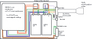
| 1 | DIY raw dc psu |
|
This
is the psu you want if you are going to use onboard regulators in the
preamp or for the ultra preamp project (see the preamp page). It provides
2 seperate raw DC feeds to the preamp and forms the basis of your powersupply. If
you wish to supply 6 onboard regulators in your preamp then you have 2
options: Get
the buid notes here.
(word document) this should give you all the information you need to get
a supply up and running.
|
£200 | 11/10 |
| 2 | DIY Hi/super cap |
This is basically the raw dc psu (see above for all details) but with 2 superregs IN the case as opposed to in the preamp similar to the naim hicap. The pink fish OS sauce cap as diagramed at ALW audio here basically shows how to do it. If
possible again I would use the Mr Tibbs earthing mod (no1 above) as well
as the rerouting signal path mod (no2 above) and thus a 4 core ALW power
lead. However you can see from here if you want to make a DIY supercap (fig 2 above), just shove more regulators into the case. i would note that in naim pre's in general the gain boards receive half the total regulation of a hicap for themselves and the buffers, tape buffers etc get the other regulator ( front to back regulation) i.e. the gain boards are the most sensitive and responsive part of the preamp. You'll then probably want to use an 8 pole speakon interconnect with 8 core interconnect (6 rails plus 2 grounds) or the multipin burndy sockets.
|
xyxyxy | 8/10 | |
| 3 | DIY napsc | The Les Wolstenholme DIY snaps |
The Snaps is a small outboard supply that can be used to feed the digital circuits (switching, remote etc) in a NAC102/NAC82. Its essentially just a regulated supply that feeds 18V to the preamp which is then internally regulated within the pre to the required voltages.
Thanks to Les Wolstenholme |
2 | |
|
The Andy Weekes snaps
|
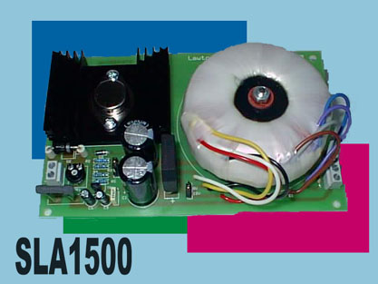
An alternative project, which is a bit more costly but does the same thing and looks great, is thanks to Andy Weeks, originally posted on the pink fish forum: Left is
the Lawtronics SLA1500 sealed lead-acid, current limited charger. It's
basically a PCB containing toroid / rec / smoothng + an LM317K with heatsink
(size: 44x100x160). They are available from Farnell, in a couple of flavours,
the 12/24V being the one to go for. The farnell p.no. for the charger
unit is 4271040, and they are £42.65 each. Thanks to Andy Weekes |
||||
|
Interconnects, Power umbilicals, Plugs and sockets |
||||||
Priciple
of interconnects
|
||||||
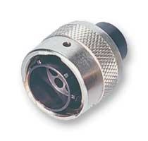
Bullet plugs |
If using rca connectors, bullet plugs are pretty universally acclaimed as the best out there by a long way (make more of a difference than expensive cables according to some) so it would seem sensible to always use these. These work on a similar principle to din plugs as well. They look cheap but who cares if they sound that good. They also now sell a silver version but I doubt they have much in the way of sonic gains and they are stupidly expensive. |
|||||
| din plugs |
Naim
use those as listed in the components page. Which pin does what can be
read off the back of the naim gear as it is clearly indicated there but
for reference its here below: |
|||||
 |
 |
 |
 |
|||
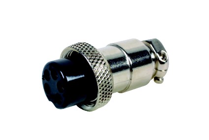
| Simple
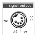
signal interconnects (e.g. from cd player to preamp) use 5 pin 180
degree din plugs/socket. (Beware there is also a 240 degree version
of the 5 pin socket). Has a ground and 2 signal channels. |
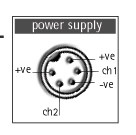
Powersupplies
(e.g hicap to preamp) use 5 pin 240 degree
plugs and sockets. (Beware there is also a 180 degree version of the 5 pin
socket). They have a ground line, 2 signal channels and 2 x 24V power lines. |
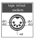
Poweramp to preamp use 4 pin din plugs/sockets. These have a ground line, 2 signal channels and a 24V powerline from the poweramp to the preamp. | Tape din sockets have in and out on the same socket as above.These are 180o 5 pin din sockets!!!! | |||
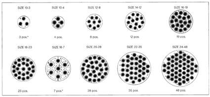
| Burndy plugs |
Naim use these on their high end gear for interconnects between their psus and equipment i.e supercap to nac52, 500psu to Nap500 etc . They are the Metalok Bantam series now produced by FCI (formerly Burndy).
|
|||||
| The preamp burndy use the 19 pin shell and sockets. Not sure about the CD players. | The nap 300, 500 etc use the 7 pole sockets and plugs with relevant pins |
Apparently
these require a special insertion tool to
place the pins in the sockets and extract them. Bear in mind the pins
take 1.5mm cable max. You will want to solder the cable to the pins not
crimp them.
|
||||
|
|
||||||
| Neutrik plugs |
My preference is to use the Neutrik 4 and 8 pole sockets/plugs for psu umbilicals. They also have an impedance of <3mohm but accept large diameter cable (over 2.5mm) so you can use very heavy gauge and therefore low impedance cables for psu power umbilicals: Also the pins are molded in the sockets so you don't have to fool around with insertion tools etc and they have screw terminals. This means its easy to screw in the cables into each pin socket to fix them into position and THEN solder them in for a low impedance connection. Use a good 40W soldering iron for this. |
|||||
|
8 Pole neutrik for power on a CD3.5 |
get datasheet on neutrik 8 pole speakon sockets here get datasheet on neutrik 8 pole speakon plugs here see components page for ordering information. |
|||||
|
Power
Umbilical |
|||
| Mod | Comments and information | Construction | |
|
ALW psu power lead
Snaic and ALW 3 core powerlead on a CD3.5 with red heatshrink. |
This is basically for connecting the cd3/cd3.5/cd5 to an external psu or psu to preamp powerfeed if doing the 'rerouting signal path' mod no2 above. Gives a noticeably more solid and dynamic sound and is just better all round. |
Use
2 normal 5 pin din plugs as per components list and a meter of the flexible,
3 core 1.5mm mains cable available from B&Q. Solder as per the 5 pin
din socket diagram above. Note it is a thick cable and a very tight fit
so you will have to strip back 10cm or so of the outer sleeving at each
end and reseal with heatshrink tubing to allow the wires to go through
the plugs. Use 1.5 -2cm diameter heatshrink. This is how naim used to
do it with grey powersnaics also. So you'll need 2 x 5pin, 240o din sockets and just over a meter of 3 core or 4 core wire. If using 4 core cable (to make use of the Mr tibbs earthing mod) you will only be able to fit 4 core 1mm2 cable in a din plug. see recommended parts page for order numbers etc. Thanks to Andy Weekes |
~£6 |
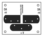
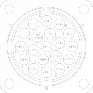 This
is the pin voltage and channel configuration for the NAC52 burndy
This
is the pin voltage and channel configuration for the NAC52 burndy