Inveterate meddling #379: Quick notes on using voltage regulators, Part 3
Or, why low-ESR capacitors can be a Bad Thing.
Time to look at the effect of picking the wrong capaciator to hang off the output of a voltage regulator. The wrong caps to use are 'low-ESR' types.
- Where 'low'-ESR' is only what it takes to upset a voltage regulator!
OK, not helpful: there is a nice pictorial illustration here.
Remember how a regulator works? An error amplifier tries to force the output up or down by comparison with an internal reference. As the error amplifiers gain falls off with increasing frequency, so too does the regulators accuracy and output impedance. This rise in output impedance with frequency then looks just like an inductor - and that is how it behaves: as a synthesised inductor.
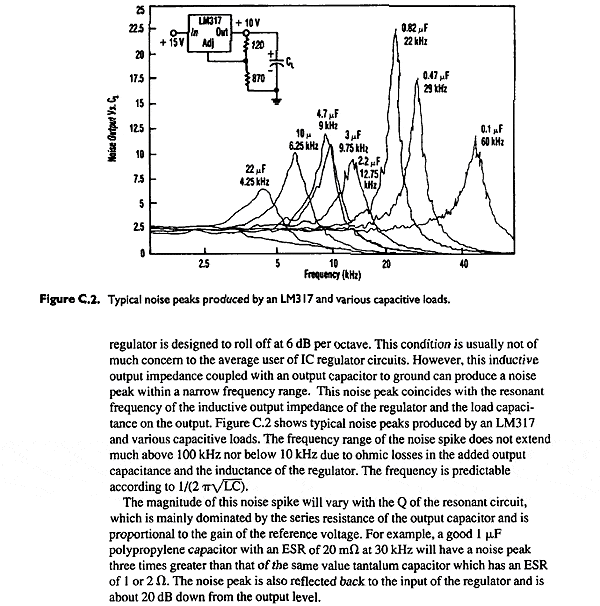
Here is an extract from a National Semicondor App Note by Eric Dietz (to be uploaded here). Read it carefully:

At the output of a regulator, then, using a cap with too low an ESR risks forming a 'peak ' in the overall response, because it can resonant with this inductive output impedance. The ESR of this cap also affects the 'Q' or peakiness of this rise.
So, looking again, what sort of ESR do capacitors display? Here's a rough guide:
Larger caps will have lower ESR, but ESL will be higher and dominate at higher frequncies. You can't win in this game! One last little wrinkle: the ESR of electrolytic caps drops with temperature...
Now, why do we care: well let's take a look at the humble LM317 3-pin regulator as a starter:

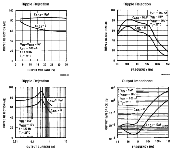
From the graph of output impedance vs/ frequency (bottom-right) we can derive that the LM317 reg has an effective output inductance of about 5uH with the 'Adjust' pin bypassed as per datasheet. So for a given cap on the output - say 47uF:
Impedance at resonance Z= SQRT(L/C) = SQRT(5uH/47uF) = ~0.3R.
Hence a good-quality electrolytic cap of 0.3ohm ESR will be critically damped; and cheapo electrolytic, Zc=1ohm, will be more-than critically damped (Q<0.7, a Good Thing) but a 47uF Oscon, maybe 0.015ohm ESR, represents a high-Q circuit (Q ~20) at f = 1/ (2*pi*SQRT(L*C)), about 10Khz, or a tendency to ring at that frequency. That may or may not be perceptible as a somthing like forward /sibilant treble if used as the PSU for an a linear audo stage.
Now try the numbers for the 1uF cap shown in the original National Semiconductor LM117 datasheet on Page 1 and you'll find X=2.7ohm - which is exactly the resistor value they show in series with the 'ideal' cap, with no explanation why... If you still haven;t got it - take another look at the graph at the top of the page for values around 1uF. Damping matters.
A couple of notes to finish: Arbitrarily-high ESR is not necessarily a good thing, either: it can even lead to instability. So don't go adding small series reisstors without some thought. This especially applies to low-dropout types, which use this cap to create a pole in the error amplifiers response. Check the datasheet - the ESR or size of the output cap may be required to be in a certain critical range for stability, and this will be identified on a graph if so.
What about Cadj then..?
How far is too far? and is a low ESR cap a bad idea in this position? Well, the cap only needs to be big enough to put the rolloff right down at the bass end of the spectrum, preferably below the audio band IMO and so it depends on the lower voltage set resistor.
Notithstanding what I wrote in part one, for almost all purposes 10uF is more than enough for Cadj. Using, say 1K5 as the lower voltage-set resistor that's -3dB at 1/(2*pi*10uF*1500) = 10Hz. With smaller Rset values (for lower voltages output) you might go bigger, but it's unlikley that you need more than 47-100uF. (I suggest if you go much bigger than 10uF you should add the reverse-bias protection diodes shown on the datasheet, particularly with LM337s - it seems easier to kill these than 317s)
Now - Cadj works because it is a very small reactance compared with R2. Therefore, going for a (more expensive) low-esr cap doesn't actually buy you ...any real performance benefit; the difference between say ESR = 1ohm and ESR=0.1ohm is negligable. So low-ESR doesn't seem to matter here, neither is it particularly worth using an expensive/boutique cap.
That said - when used in the pre-reg in a tracking preregulator setup it does seem that ESR here DOES affect overall stability... on to Part Four!
© 2006 the twisted pair