Inveterate meddling #3802 Quick notes on using voltage regulators, Part 4
Or, why Tracking Pre-regulators are a Good Thing - if you are careful
Now - overdue - let's look at the effect of cascading generic 3-pin regulators.
The common wisdom is that cascading series regs means you just add up the individual contributions for a glorious total that's easy to achieve, because the performance of each reg just adds up, right? Well, not quite. In a series cascade of regulation, the second reg is fed a near-constant voltage, and tries to maintain a near-constant output voltage, but the two are not related. Consequently there's are small error term between its own input and its output which depend on both load and line(supply)-related activity. Meanwhile the incoming noise rejection performance we looked at in part two is no better, and the noise contribution from each reg in series adds up , more or less.
So - in what way can we usefully cascade regs, if at all? Well try this, also contained in the LM317 datasheet:
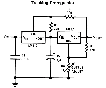
Look at how the tracking -pre-regulator works: it does *not* fed the second reg with a voltage regulated relative to input ground. Instead it maintains a contant voltage across the second regulator. Which is a subtle but important improvement: the second reg has a constant voltage across it, so the error amp inside it is ONLY dealing with load regulation. The line regulation issue - dealing with incoming noise - is solely the job of the first regulator. That's a very different case to the series cascade, where both regs have to deal with line. And the improvement can be audible in my experience.
The datasheet supplies the diagram, but doesn't explain it at all, which is a shame because there is a hidden wrinkle to iron-out if the TPR is to perform optimally.
First: if adding a cap across R2 helps the ordinary 317, why is none shown for the input reg here? Can we add one and make it work?
Yes. And no, not without a little more effort. Here's the resulting diagram:
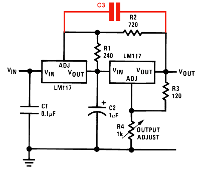
Do this, and depending on the values you pick for these caps you can find the TPR is anything from marginally to quite unstable, develops a lot of overshoot on step changes and performs badly enough to 'sound' poor. The clue comes from looking at the diagram in a simplified manner:
Here's our new cap across R2 'C3'. This creates a network R1C2,R2//C3 feeding a high-impedance input to an element with gain (the second LM317). That is, R1C2, R//C3 along with some gain contributed from the first reg essentially forms the basis of a classic form of oscillator, the Wien Bridge. In fact using teh maths of wien bridges agrees very well. For the given datasheet values, using 47uF for our new C3 pushes the potential 'peaking' down to below 18Hz, and I'd recommend this or larger (100uF of cheap electrolytic works well). This helps guarantee the thing won't actually ring; but try it with a 1uF film cap for C3 and you can get a large observable peak round 600Hz-1Khz (depending on tolerances of other parts for values given)
Fortunately the way to deal with oscillation is to add damping:
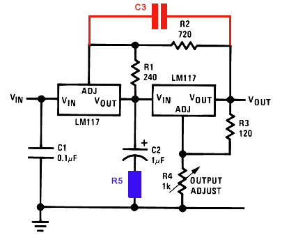
This simple addition really helps and I'd recommend it in even the most basic TPR implementation, whether or not you add 'C3'. As to typical values ror C2 = Polyester 0.1uF in series with R5= 10ohms, or C2=1uF in series with R5=2R7 - 3R3; or a cheap 10uF electrolytic cap all work well here. Do not use fancy boutique low-esr caps on their own!
Finally, and most obviously - we can totally avoid the problem by not adding that extra bypass cap in the first place! We only need to maintain at least 2.5v across the second reg - how about learning from part 1 and using a low-noise voltage reference instead say an LED, like this:
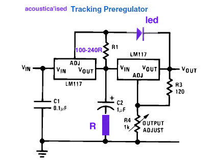
There, we've got rid of a cap and a resistor by using a cheap red or green LED drops c.2.8-3v across reg2, which absolutely minimises noise from the first reg because the led at 5-10ma has a dynamic impedance under 30ohms. The added resistor still critically-damps the input to the second reg, stopping any spurious oscillation due to high loop gain / layout strays. And of course you can play with zeners and added caps etc in palce of R4on the second reg as described previously.
So - a composite regulator with about 100dB of line rejection, a separate reg which essentially only deals with load rejection, 1.5A output capacity, short-circuit protection built-in, and it only costs pennies and requires about 5volts of 'headroom'. If you just want a quick and dirty implementation and can spare more voltage overhead you can use regular 3pin regs like the 7805 for the first reg, and just omit R1 and R2 altogether. A circuit well worth playing with for the very low cost of entry!
© 2006-11 the twisted pair